Instruction Manual
Page 14 of 40 Issue: 2.1
N:\Engineering\Manuals\Pump Unit E2-30 & 40 R2.1.doc
Installation – Section 3.3 - Mechanical
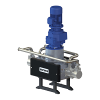
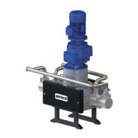
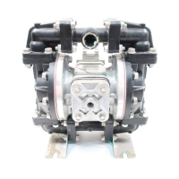
• Secure the Pump assembly to the floor (or purpose designed support
steelwork) using the 4 off Ø13 mm holes in the base of the pump support
frame.
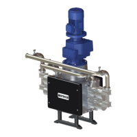
• Attach suitable hoses (20 bar maximum working pressure) to the inlet and
outlet connections. E.g. 50 mm NB Inlet and 38 to 50 mm NB Outlet hose.
• In addition to the pressure switch a Pressure relief valve can be connected
and piped back to the pump supply tank to relieve pump outlet pressure in the
event that the pipework system is closed (by ball valve or other means)
causing system overpressure.
This is necessary to protect the Pump mechanics from overload and
subsequent damage.
It is recommended that the relief valve setting is set to 1 bar (14.5 psi) above
the maximum required pressure. The maximum Pressure setting the relief
valve should be set to is 1 bar (14.5 psi) above pump maximum working
pressure.
A pressure sensor is utilised when the pump is set up in ‘Pressure Mode’
(instead of ‘Stroke Mode’) where the pump cycle rate is adjusted to respond to
paint system pressure, a dedicated ‘Smart Card’ or PLC software should be
incorporated in the pump control system to ensure correct operation.
• Ensure adequate air space around the Pump for maintenance and electric
motor cooling requirements.
• Check that the oil plug on top of Gearbox has been replaced with the correct
venting plug. The vent plug is supplied in a bag attached to the gearbox.
• Ensure the gearbox is filled with oil. (The gearbox is filled with the correct
amount of oil at the factory)