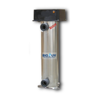
BIO-UV
Copyright BIO-UV 03/07/08
3
We thank you for choosing a BIO-UV ultraviolet water treatment system.
Our equipment has been designed to offer you operational reliability in total confidence
for many years.
CONTENTS
Page
Warnings and safety 4
Exploded view
5
Detailof the parts
6
Parts list
7
Dimensions
7
Standard installation
8
Electrical Connections
9
Wiring Diagram
11
Maintenance
12
Guarantees 13
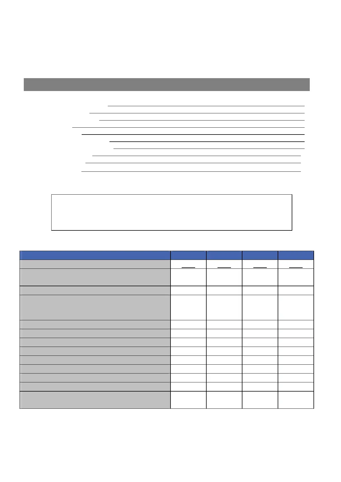
DESCRIPTION UV 10 UV 20 UV 30 UV 40
Maximum pressure in Use
3Bar
3Bar 3Bar 3Bar
Maximum flow rate (m
3
/h)
(after pressure losses)
7 12 20 28
EXPOSITION TIME / secondes
2,8” 2,6” 2,3 2,1
PERFORMANCE In millijoules at the actual flow
rates recommended above.
(mandatory standard for drinking water: 25mj)
25 mJ 25 mJ 25 mJ 25 mJ
BALLAST
1111
LAMP (nomber and power)
1 x 33 W 1 x 55 W 1 x 87 W 1 x 114 W
SERVICE LIFE of LAMPS
13 000 h 13 000 h 13 000 h 13 000 h
DIMENSION of the UV CHAMBERS in cm
32 58 83 108
DIAMETER of the UV CHAMBERS in cm
15 15 15 15
OVERALL HEIGHT in cm
42 69 94 120
WEIGHT POIDS (without water) kg
7,6 9 11 14
CAPACITY IN LITRES
6,40 11,70 17,30 22,40
INPUT/OUTPUT (diameter in mm)
with Unions supplied
50 50 63 75
The BIO-UV equipment is ready to be installed.
No intervention is required inside the equipment.
A simplified quick assembly procedure is provided.