2. CLINICAL CONSIDERATIONS FOR GENERAL USE
— 2-3 — CLINICAL CONSIDERATIONS FOR GENERAL USE
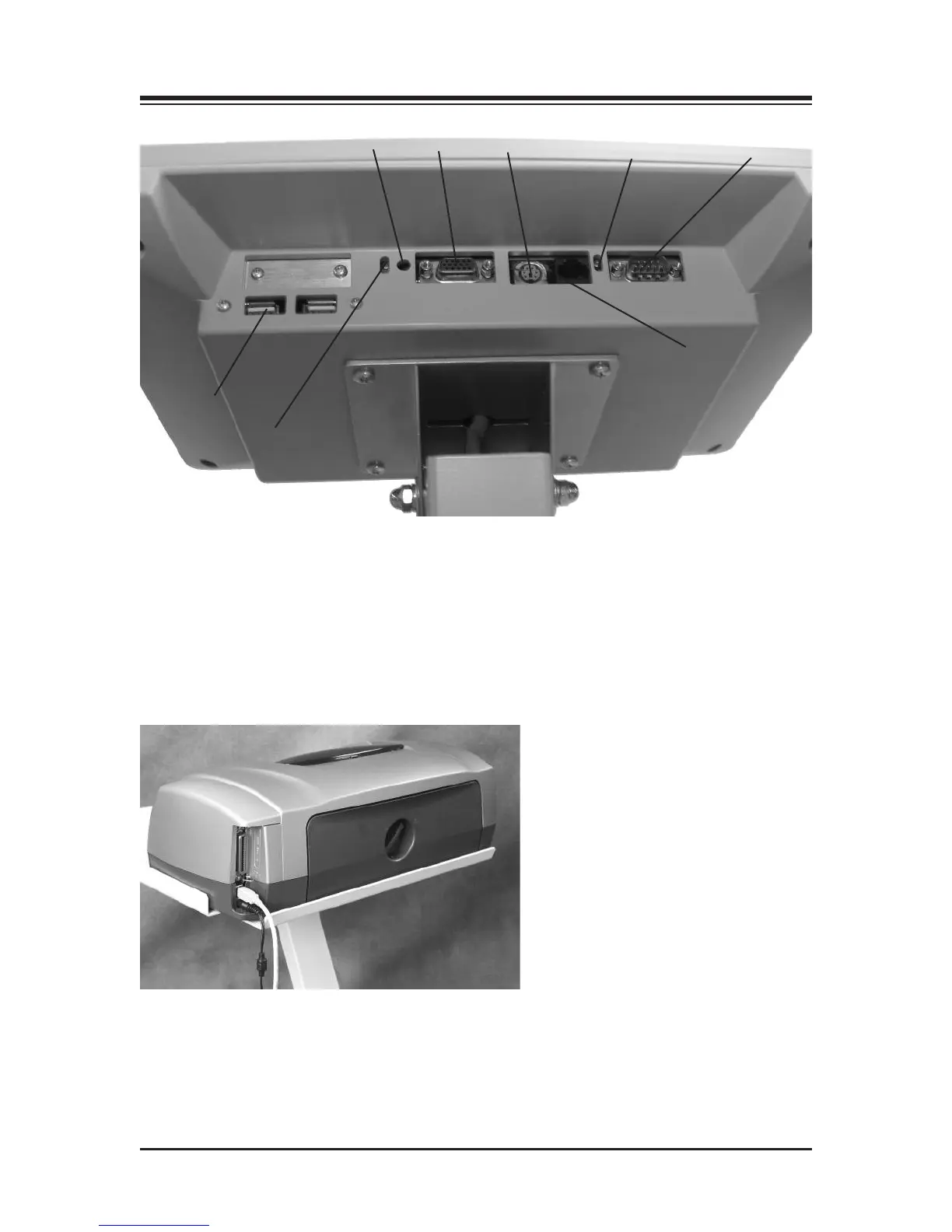
Figure 2.1.
1. Reset Button
2. Remote CRT Monitor Connector
3. PS 2 Connector
4. Ethernet activity lights. Green indicates connectivity. Yellow indicates activity.
5. Auxiliary Com Port (Serial Port)
6. Ethernet Connector (RJ 45)
7. PCB activity lights. Green indicates compact flash activity. Yellow indicates power on.
8. USB Connectors (suggested to use one of these for printers)
Figure 2.2. Connect the power cable and USB cable to the rear of the printer.
The printer power cable should only be plugged into the dedicated AC receptacle located at the
front of the base. A special IEC adapter cable is provided.
The printer USB should be plugged into one of the USB ports on the side or bottom of the display.
1
2
3
4
5
6
7
8