BCS-8xx series installation manual
9
Table 3: Detailed BCS-805 front panel description
Cell on/off :
Button with LED, when blue, the
voltage cell power is ON
Ventilation grid:
Air moves through the openings
Channel number with status
channel LED indicator. Detailed
description, see below.
Cell channel connectors:
4 pins horizontal connectors and
Ground connector.
For low current values (BCS-805 and BCS-810) each cell channel connectors includes a
shielding pin which provides protection from electrostatic interference. This shield is con-
nected to chassis ground.
LEDs associated to each channel are present
on the front panel (1 to 8). These LEDs indi-
cate the status of the channel as follows:
Green: Discharge regime/OCV/EIS
with a discharge regime
Orange: Charge regime/EIS with a
charge regime.
LED Off: channel stopped
Flashing Red: channel error
The channel error (blinking red led) may be
due to:
- A cell voltage higher than 10V
- A cell voltage lower than 0 V
- A internal heat sink temperature
higher than 70°C
- Potential or current control problem
(e.g. a disconnected cell)
- When the Open In stops the meas-
urement (optional)
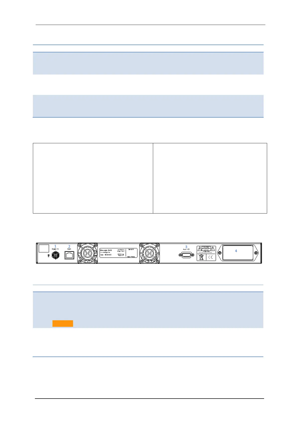
1.2.2.2 BCS-805 rear panel detailed description
Figure 7 below corresponds to a scheme of the rear panel of the BCS-805. Detailed descrip-
tion is given in table 4.
Fig. 7: BCS-805 rear panel detailed description.
Table 4: Detailed BCS-805 rear panel description
Open IN:
Open relays of all the channels
when contact closed or logical
zero input (TTL level)
Caution: 5.5VDC max!
Com:
Communication input, should be con-
nected to a RJ45 port of the BCS-COM
(refer to the appropriate module letter)
Aux I/O:
DB9 connector with Analog and
digital Inputs & outputs
Power Line:
Power entry module (IEC320 C13 + fus-
es + switch on/off) for power control
part.