BCS-8xx series installation manual
13
1.2.4.1 BCS-815 front panel detailed description
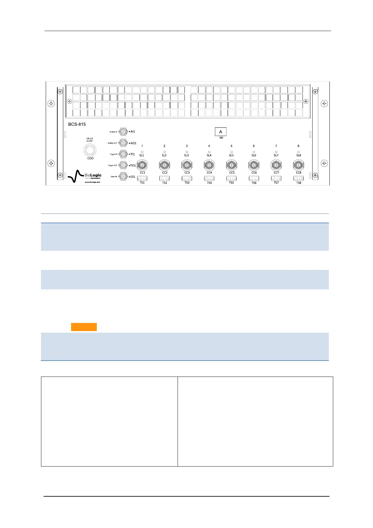
Figure 12 below corresponds to a scheme of the front panel of the BCS-815. Detailed de-
scription is given in table 7.
Fig. 12: BCS-815 front panel detailed description.
Table 7 : Detailed BCS-815 front panel description.
Cell on/off :
Button with LED, when blue, the
voltage cell power is ON
Analog input:
± 5 Vmax, 18-bits resolution
Analogic output:
± 5 V, 16-bits resolution
Trigger in:
TTL level trigger input
Trigger out:
TTL level trigger output
Open IN:
Open relays of all the channels
when contact closed or logical zero
input (TTL level)
Caution: 5.75 VAC max !
Status channel LED indicators:
Detailed description, see below.
Cells channel connectors:
7 pins circular connectors.
Thermocouples input, Type K,
Accuracy: ± 2°C, Measurement
range: -25/+200°C
LEDs associated to each channel are pre-
sent on the front panel (SL1 to 8). These
LEDs indicate the status of the channel as
follows:
Green: Discharge regime/OCV/EIS
with a discharge regime
Orange: Charge regime/EIS with a
charge regime
LED Off: channel stopped
Flashing Red: channel error
The channel error (blinking red led) may be due
to:
- A cell voltage higher than 10V
- A cell voltage lower than 0 V
- A internal heat sink temperature higher
than 70°C
- Potential or current control problem (e.g.
a disconnected cell)
- When the Open In stops the measure-
ment