12
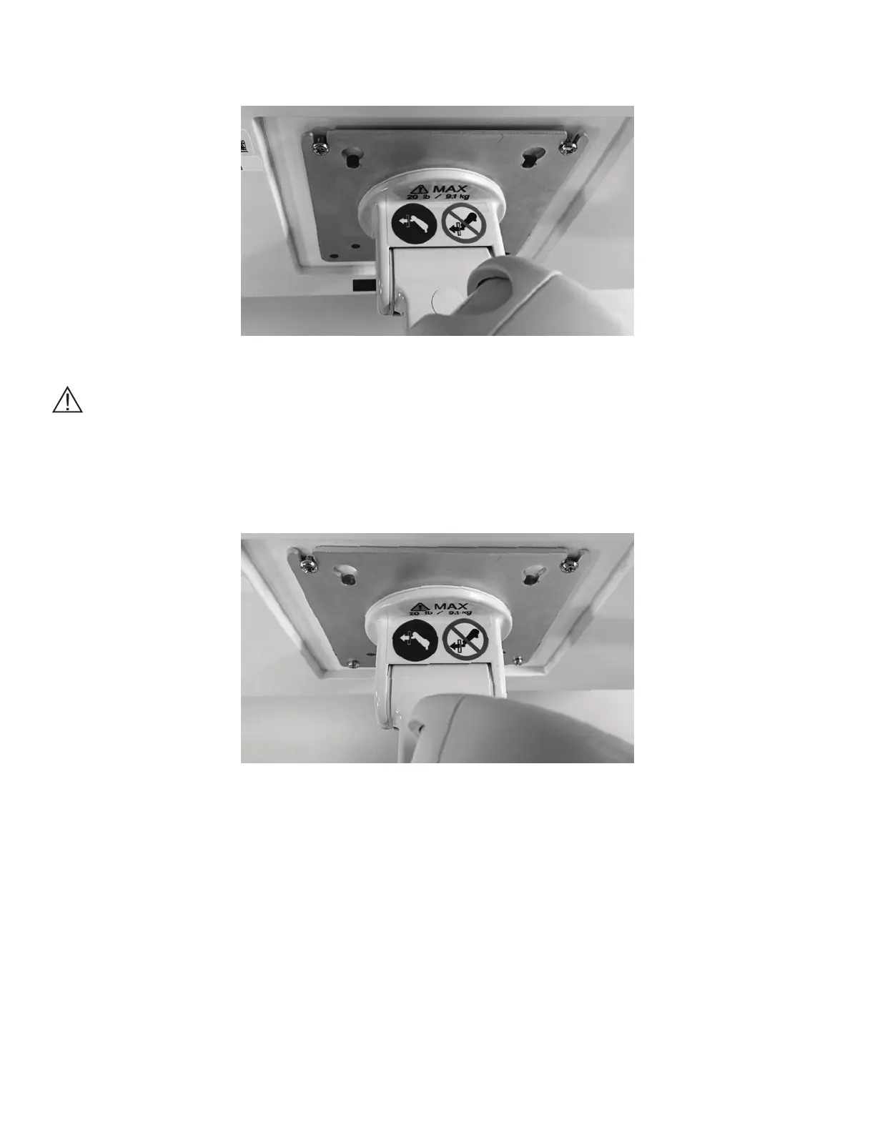
4. Slide the top Mounting Screws into the slots on the top of the VESA Mounting Plate on the Variable Height
Arm. See Figure 4.
Figure 4: Top Mounting Screws Inserted into VESA Mounting Plate.
Caution: The Variable Height Arm is designed to dynamically support the weight of the Touchscreen PC.
The arm may move down as the weight of the Touchscreen PC is transferred to it. Use caution, and perform
Step 4 slowly.
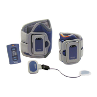
5. Replace the Mounting Screws on bottom of the VESA Mount, and tighten all four screws. See Figure 5.
Figure 5: Installed Touchscreen PC on VESA Mount