14 | Chapter 2: Hardware installaon
2.7 Headers & Connectors
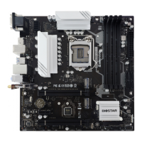
ATXPWR1: ATX Power Source Connector
For beer compability, we recommend to use a standard ATX 24-pin power supply for this
connector. Make sure to nd the correct orientaon before plugging the connector.
Pin Assignment Pin Assignment
13 +3.3V 1 +3.3V
14 -12V 2 +3.3V
15 Ground 3 Ground
16 PS_ON 4 +5V
17 Ground 5 Ground
18 Ground 6 +5V
19 Ground 7 Ground
20 NC 8 PW_OK
21 +5V 9 Standby Voltage+5V
22 +5V 10 +12V
23 +5V 11 +12V
24 Ground 12 +3.3V
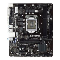
ATXPWR2: ATX Power Source Connector
The connector provides +12V to the CPU power circuit.
Pin Assignment
1 +12V
2 +12V
3 Ground
4 Ground
Note
»
Beforeyoupoweronthesystem,pleasemakesurethatbothATXPWR1andATXPWR2connectors
havebeenplugged-in.
»
Insucientpowersuppliedtothesystemmayresultininstabilityortheperipheralsnotfunconing
properly.UseofaPSUwithahigherpoweroutputisrecommendedwhenconguringasystemwith
morepower-consumingdevices.
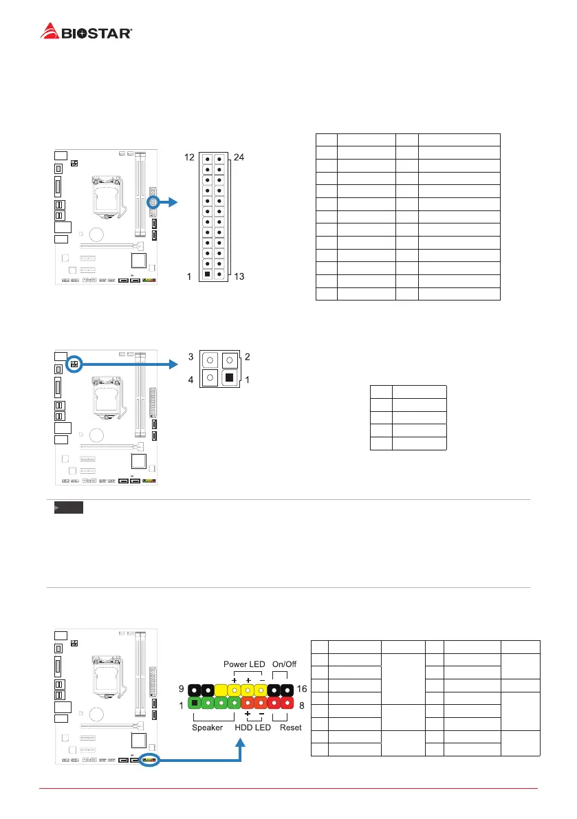
PANEL1: Front Panel Header
This 16-pin header includes Power-on, Reset, HDD LED, Power LED, and speaker connecon.
Pin Assignment Funcon Pin Assignment Funcon
1 +5V
Speaker
Connector
9 N/A
N/A
2 N/A 10 N/A
3 N/A 11 N/A N/A
4 Speaker 12 Power LED (+)
Power
LED
5 HDD LED (+)
Hard drive
LED
13 Power LED (+)
6 HDD LED (-) 14 Power LED (-)
7 Ground
Reset
buon
15 Power buon
Power-on
buon
8 Reset control 16 Ground
 Loading...