14 | Chapter 2: Hardware installaon
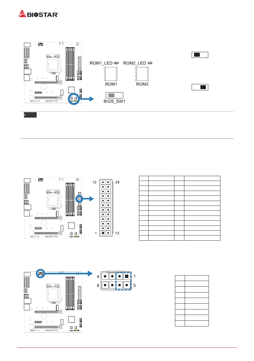
BIOS_SW1: Dual BIOS Switch
The Dual BIOS Switch allows you to choose one of the BIOS ROMs (ROM1/ROM2) for boot up.
Main BIOS (ROM1) Enabled
The LED indicator (ROM1_LED) will light
and the Main BIOS is enabled.
Backup BIOS (ROM2) Enabled
The LED indicator (ROM2_LED) will light
and the Backup BIOS is enabled.
Note
»
Donotusethisswitchwhenyoursystemispower-on.
»
BeforeashingBIOSROMs,pleasemakesurethisswitchissettotheBIOSROMwhichyouwantto
update.
2.7 Headers & Connectors
ATXPWR1: ATX Power Source Connector
For beer compability, we recommend to use a standard ATX 24-pin power supply for this
connector. Make sure to nd the correct orientaon before plugging the connector.
Pin Assignment Pin Assignment
13 +3.3V 1 +3.3V
14 -12V 2 +3.3V
15 Ground 3 Ground
16 PS_ON 4 +5V
17 Ground 5 Ground
18 Ground 6 +5V
19 Ground 7 Ground
20 NC 8 PW_OK
21 +5V 9 Standby Voltage+5V
22 +5V 10 +12V
23 +5V 11 +12V
24 Ground 12 +3.3V
ATXPWR2: ATX Power Source Connector
The connector provides +12V to the CPU power circuit. If the CPU power plug is 4-pin, please
plug it into Pin 1-2-5-6 of ATXPWR2.
Pin Assignment
1 +12V
2 +12V
3 +12V
4 +12V
5 Ground
6 Ground
7 Ground
8 Ground
»
ConnuedonNextPage
 Loading...