B75MU3+
13
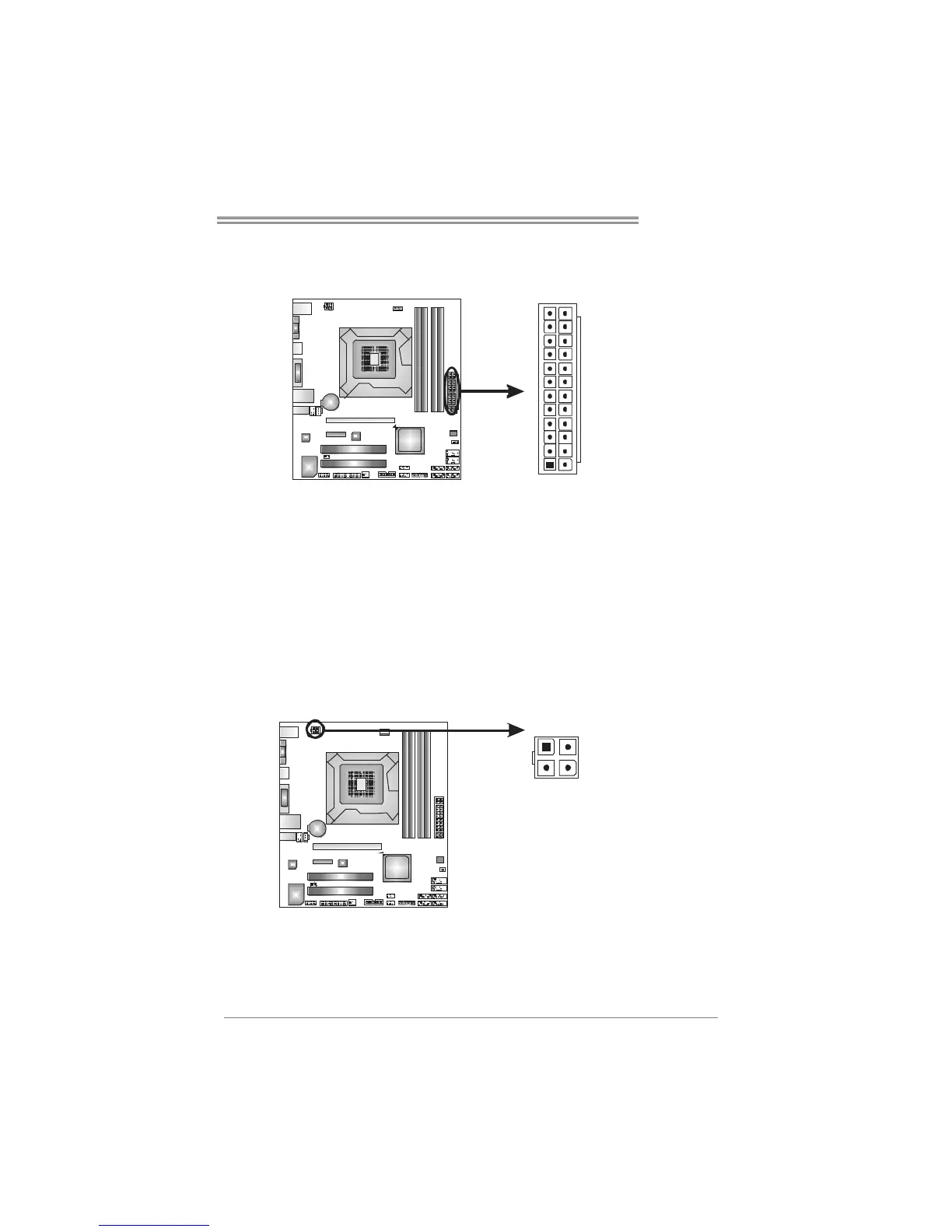
ATXPWR1: ATX Power Source Connector
This connector allows user to connect 24-pin power connector on the ATX
power supply.
1
12
13
24
Pin Assignment Pin Assignment
13 +3.3V 1 +3.3V
14 -12V 2 +3.3V
15 Ground 3 Ground
16 PS_ON 4 +5V
17 Ground 5 Ground
18 Ground 6 +5V
19 Ground 7 Ground
20 NC 8 PW_OK
21 +5V 9 Standby Voltage+5V
22 +5V 10 +12V
23 +5V 11 +12V
24 Ground 12 +3.3V
ATXPWR2: ATX Power Source Connector
This connector provides +12V to CPU power circuit.
Pin Assignment
1 +12V
2 +12V
3 Ground
1
23
4
4 Ground
Note:
Before you power on the system, please make sure that ATXPWR1 and ATXPWR2
connectors have been well plugged-in.
 Loading...