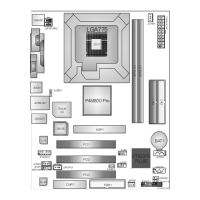
P4M80-M4
14
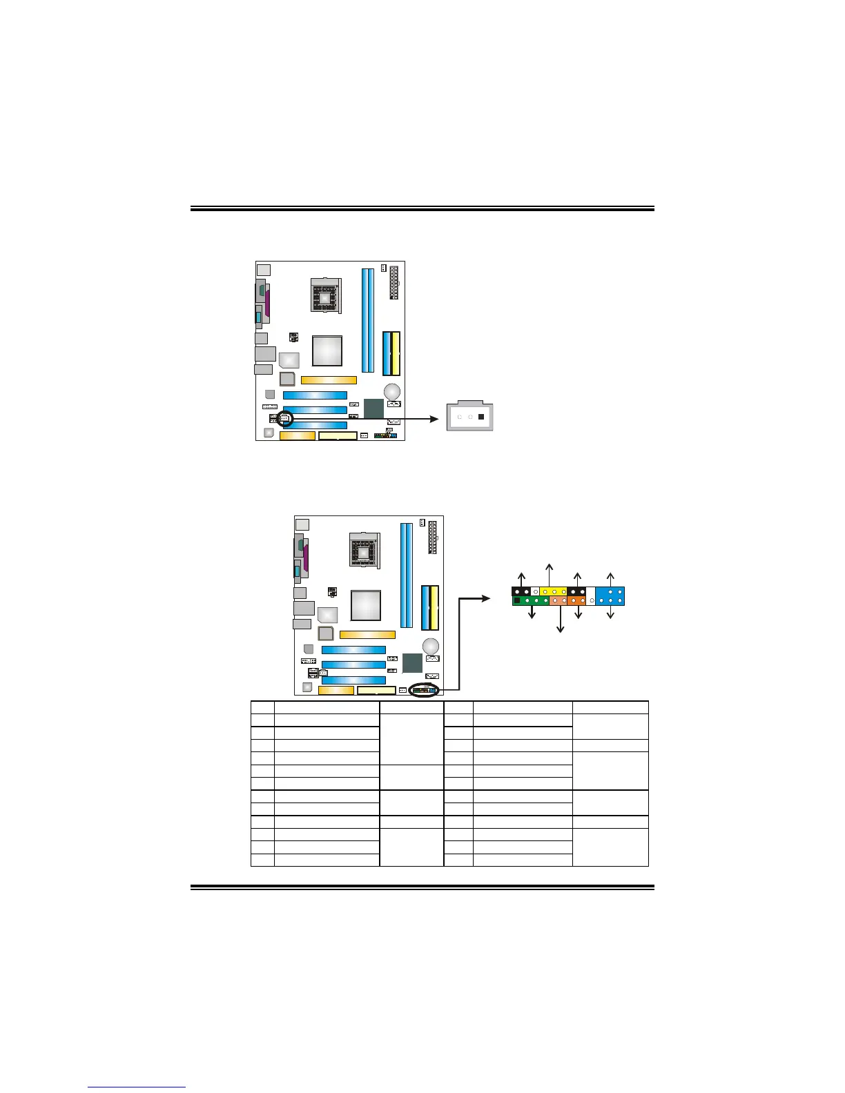
JSPDIFO1: Digital Audio-out Connector
This connector allows user to connect the PCI bracket SPDIF output header.
Pin
Assignment
1 +5V
2 SPDIF_OUT
1
3
PU
3 Ground
JPANEL1: Front Panel Header
This 24-pin connector includes Power-on, Reset, HDD LED, Power LED, Sleep
button, speaker and IrDA Connection. It allows user to connect the PC case’s
front panel switch functions.
1
23
24
SLP
PWR_LED
On/Off
IR
IR
RST
HLED
SPK
++
+
2
-
-
PU
Pin Assignment Function Pin Assignment Function
1 +5V 2 Sleep control
3 N/A 4 Ground
Sleep button
5 N/A 6 N/A N/A
7 Speaker
Speaker
Connector
8 Power LED (+)
9 HDD LED (+) 10 Power LED (+)
11 HDD LED (-)
Hard drive
LED
12 Power LED (-)
Power LED
13 Ground 14 Power button
15 Reset control
Reset button
16 Ground
Power-on button
17 N/A 18 Key
19 N/A 20 Key
21 +5V 22 Ground
23 IRTX
IrDA
Connector
24 IRRX
IrDA Connector
 Loading...