EasyManua.ls Logo

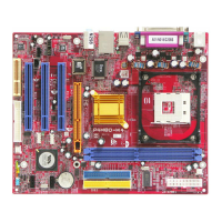
Biostar P4M800

Biostar P4M800
51 pages
Go to English
To Next Page IconTo Next Page
Loading...
P4M800 Pro-M7 Setup Manual
FCC Information and Copyright
This equipment has been tested and found to comply with the limits of a Class
B digital device, pursuant to Part 15 of the FCC Rules. These limits are designed
to provide reasonable protec tion against harmful interference in a residential
installation. This equipment generates, uses and can radiate radio frequency
energy and, if not installed and used in accordance with the instructions, may
cause harmful interference to radio communications. There is no guarantee
that interfe rence will not occur in a particular ins tallation.
The ve ndor makes no re prese ntatio ns or warranties wi th respec t to the
contents here and specially disclaims any implied warranties of merchantability
o r fi tness fo r a ny pu rpos e . F u rthe r t he ve nd or rese rves t he ri ght to rev ise t his
publication and to make changes to the contents here without obligation to
notify any party beforehand.
D uplication of this publicatio n, in part or in whole , is not allowed without first
obtaining the vendor’s approval in writing.
The content of this user’s manual is subject to be changed without notice and
we will not be responsible for any mistakes found in this users manual. All the
brand and product names are trademarks of their respective companies.
Questions and Answers:

Biostar P4M800 Specifications

General IconGeneral
Form FactorMicro ATX
SocketSocket 478
Memory TypeDDR
Max Memory2GB
PCI Slots3
PCI Express x16No
CPU SupportIntel Pentium 4/Celeron D
FSB800MHz
Memory Slots2
IDE2
SATA2
AGP Slot1 (AGP 8X)
Audio6-channel
LAN10/100 Mbps

Summary

FCC Compliance and Copyright Notice

Introduction to the Motherboard

Pre-Installation Checklist

Provides essential pre-installation preparation steps for safe and effective motherboard setup.

Included Package Contents

Lists all components included in the motherboard package for verification before installation.

Detailed Motherboard Specifications

Rear IO Panel Connections

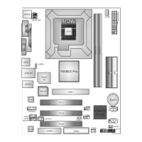
Motherboard Component Layout Diagram

Chapter 2: Hardware Installation Guide

CPU Installation Procedure

Step-by-step guide for safely installing the CPU into its socket on the motherboard.

CPU and System Fan Header Connections

Details the purpose and pin assignments for CPU and System Fan Headers.

System Memory (RAM) Installation

Instructions for installing RAM modules into the DIMM slots and memory capacity information.

Storage and Expansion Connectors

Explains the FDD connector and Hard Disk connectors (IDE1/IDE2) for storage devices.

PCI Expansion Slots

Describes the standard PCI slots for expansion cards.

AGP Graphics Slot

Details the AGP slot for video cards, enhancing graphics performance.

CNR Slot for Network Devices

Explains the CNR slot for riser cards, primarily supporting modems.

Chapter 3: Connector and Jumper Configuration

Jumper Setup Guide

Illustrates how to correctly set up jumpers by placing or removing the jumper cap.

Connector Pinout and Function Details

Provides detailed pin assignments and functions for various motherboard connectors.

Front Panel Header (JPANEL1)

Details the 24-pin connector for front panel switches and LEDs like Power, Reset, HDD LED.

20-Pin ATX Power Connector (JATXPWR1)

Describes the 20-pin ATX power connector for supplying power to the motherboard.

4-Pin ATX Power Connector (JATXPWR2)

Explains the 4-pin connector for providing additional +12V power to the CPU.

USB 2.0 Front Panel Headers (JUSB2 JUSB3)

Details headers for connecting front panel USB 2.0 ports and internal USB devices.

USB Power Source Headers (JUSBV1 JUSBV2)

Explains jumpers for controlling USB port power source (normal/standby).

Front Panel Audio Header (JFAUDIO1)

Describes the header for connecting front panel audio output and disabling rear audio.

CD-ROM Audio Input Connector (JC DIN1)

Explains the connector for inputting audio from CD-ROM, DVD-ROM, or other devices.

Clear CMOS Header (JCMOS1)

Details the header for resetting BIOS settings and CMOS data to default values.

Serial ATA (SATA) Connectors (JSATA1 JSATA2)

Describes the SATA connectors for connecting SATA hard drives and their specifications.

Digital Audio Output Connector (JSPDIFO1)

Explains the connector for digital audio output via SPDIF bracket.

Optional Chassis Intrusion Header (JCI1)

Details the optional header for monitoring PC case open status.

Chapter 4: RAID Configuration and Operation

Supported Operating Systems for RAID

Lists supported operating systems for RAID functions.

Overview of RAID Array Types

Defines the supported RAID array types: RAID 0 and RAID 1.

RAID 0: Striping for Performance

Explains RAID 0 (striping) for improved performance, detailing features, benefits, and drawbacks.

RAID 1: Mirroring for Redundancy

Explains RAID 1 (mirroring) for data redundancy and fault tolerance, detailing features and benefits.

Chapter 5: System Support and Troubleshooting

Driver CD Overview and Installation

Guides users on installing motherboard drivers from the included CD for optimal system performance.

Installing Motherboard Drivers

Instructions for installing device drivers for the motherboard and operating system.

Installing Bundled Software

Guide for installing bundled software applications from the driver CD.

Accessing the User Manual

Information on accessing the user manual provided on the driver CD, requiring Acrobat Reader.

BIOS Beep Codes for Troubleshooting

Lists common BIOS beep codes and their corresponding error meanings for troubleshooting.

BIOS Update Procedure

Provides instructions for updating the motherboard's BIOS using a flash utility and floppy disk.

CPU Overheating Protection

Explains CPU overheating symptoms and provides steps to check and resolve the issue.

General System Troubleshooting

Presents common system problems and their probable causes and solutions.

Chapter 6: WarpSpeeder Utility

WarpSpeeder Utility Introduction

Introduces WarpSpeeder utility, its functions (Overclock, Overvoltage, Hardware Monitor), and protective technology.

WarpSpeeder System Requirements

Lists the operating system and DirectX requirements for installing and running WarpSpeeder.

WarpSpeeder Installation Guide

Provides step-by-step instructions for installing the WarpSpeeder utility software.

WarpSpeeder Tray Icon Functionality

Explains the function and usage of the WarpSpeeder utility's tray icon for quick access.

WarpSpeeder Main Panel Overview

Details the main interface of WarpSpeeder, displaying system info and navigation buttons.

WarpSpeeder Voltage Adjustment Panel

Describes the Voltage Panel in WarpSpeeder for adjusting CPU core and memory voltages.

WarpSpeeder Overclock Control Panel

Explains the Overclock Panel for real-time frequency adjustments and fail-safe recovery options.

WarpSpeeder Hardware Monitor Panel

Details the Hardware Monitor Panel for real-time system status, temperatures, and fan speeds.

WarpSpeeder About Panel

Describes the About Panel, showing utility version, BIOS model, and chipset details.

Related product manuals