TA970XE
15
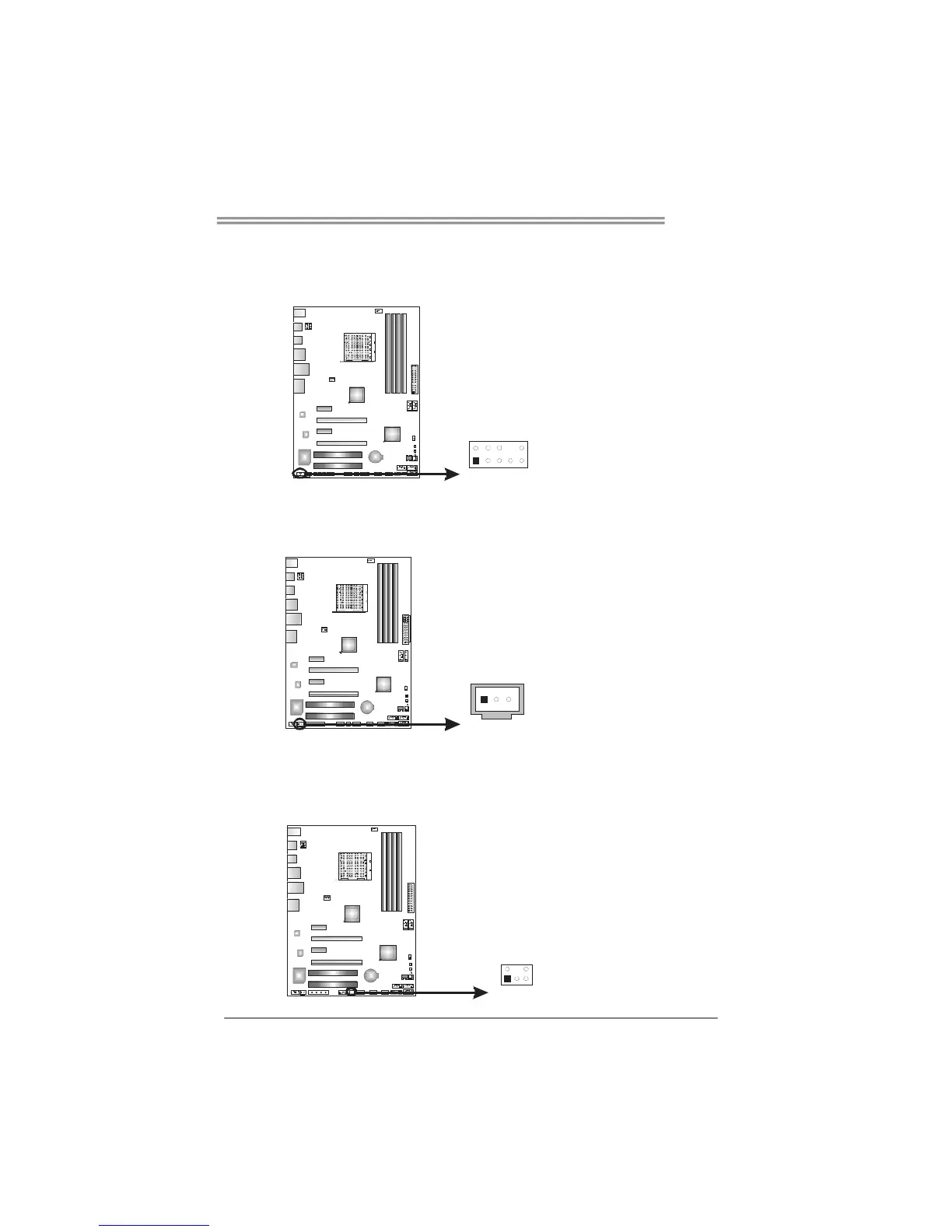
F_AUDIO1: Front Panel Audio Header
This header allows user to connect the front audio output cable with the PC front
panel. This header allows only HD audio front panel connector; AC’97 connector
is not acceptable.
Pin
Assignment
1 Mic Left in
2 Ground
3 Mic Right in
4 GPIO
5 Right line in
6 Jack Sense
7 Front Sense
8 Key
9 Left line in
10 Jack Sense
1
2
9
10
JSPDIFOUT1: Digital Audio-out Connector
This connector allows user to connect the PCI bracket SPDIF output header.
Pin
Assignment
1 +5V
2 SPDIF_OUT
3
1
3 Ground
CIR1: Consumer IR Connector
This header is for infrared remote control and communication.
Pin Assignment
1 IrDA serial input
2 Ground
3 Ground
4 Key
5 IrDA serial output
6 IR Power
1
2
5
6

 Loading...