Motherboard Manual
12
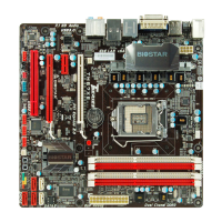
PCI1/PCI2: Peripheral Component Interconnect Slots
This motherboard is equipped with 2 standard PCI slots. PCI stands for
Peripheral Component Interconnect, and it is a bus standard for expansion
cards. This PCI slot is designated as 32 bits.
PCI2
PCI1
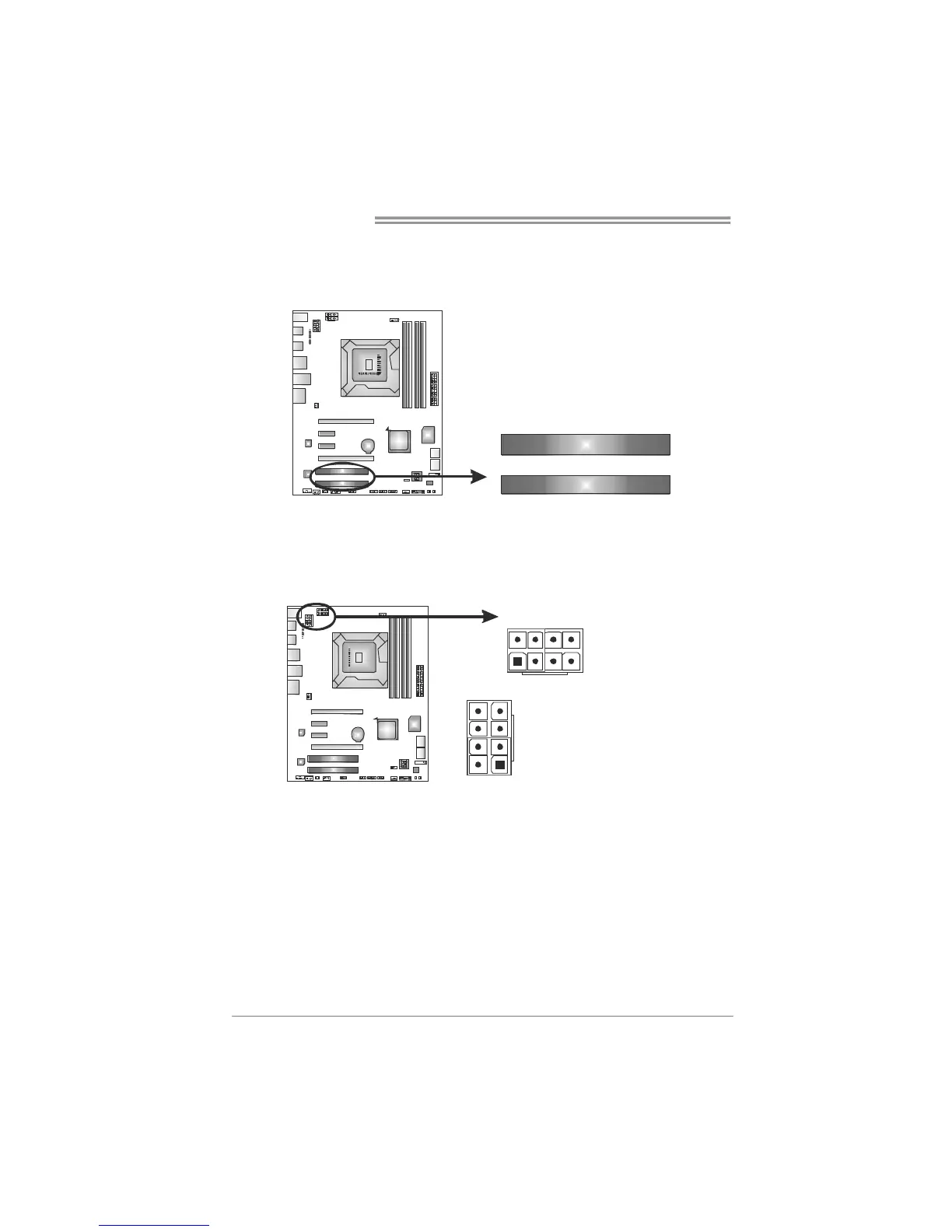
ATXPWR2/3: ATX Power Source Connectors
These connectors provide +12V to CPU power circuit. If the CPU power plug is
4-pin, please plug it into Pin 1-2-5-6 of ATXPWR2/3.
Pin
Assignment
1 +12V
2 +12V
3 Ground
14
58
1
45
8
TXPWR2
ATX P WR3
4 Ground
Note:
Generally, any of ATXPWR2 and ATXPWR3 can be plugged. When system is
overclocked, it is recommended to plug in both ATXPWR2 and ATXPWR3 for stability.