4
OPERATION
Product should be placed in the Loading Chamber with its straight side against the loading chamber wall,
toward the front edge, nearest the operator. Engage the product securely to the Product Pusher Gripper.
Product must advance toward the blade.
Turn the Main Disconnect Switch (Red Handle) “ON.”
Turn Selector switch to “RUN.”
To adjust cutting thickness: Open the Clutch Door on the right hand side of the unit.
The Thickness can be varied from
1
/16” (1.6mm) to 1⅛” (28.6mm).
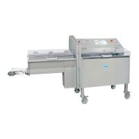
There are two Thickness Scales on the Linkage arm attached to the indexing clutch.
Scale “A”- the inside thickness scale range is
1
/16” (1.6mm) to ¼” (6.4mm).
Scale “B”-the outside thickness scale range is
5
/16” (7.9mm) to 1⅛” (28.6mm).
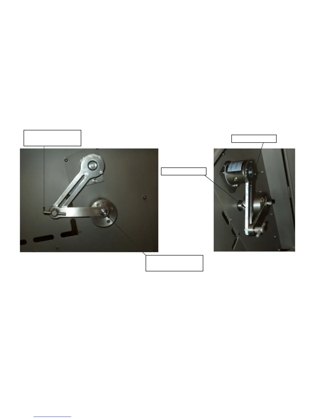
To adjust the Thickness Range on scale “A”; Loosen the
9
/16” hex head screw, item number PCM607, attaching
the Draw-Lever to the eccentric hub with a box-end wrench. Place the
9
/16” hex head screw into the threaded
hole marked “A” on the Eccentric Hub and Tighten.
The Slicer is ready for nal Thickness Adjustment.
EXAMPLE A: To obtain a ¼” (6.4mm) Thickness on the “A” scale, loosen the Linkage Arm Adjustment
Handle, item number PCM600, slide the handle with the indicator to the ¼” mark on scale “A” and tighten the
Adjustment Handle.
Adjustment Handle
Item No. PCM600
Scale “B”
Scale “A”
9
/16” Hex Head Screw
Item No. PCM607