Each time after end of machining:
➢
clean thoroughly the base guides, clamping inserts, jaws and lead
screw,
➢
pay special attention to clean the gap between clamping inserts and
jaws (L dimension on Fig. 10).
If during the clamping, inserts do not seat on jaw guides:
➢
dismantle clamping inserts,
➢
clean insert surfaces mating the jaws and cover them with some grease
➢
by means of mounting bolts set the correct position of inserts to obtain
the required value of L.
Hammering the clamping inserts or the workpiece, base guides or the
wrench when clamping is forbidden.
Do not lengthen the wrench while clamping.
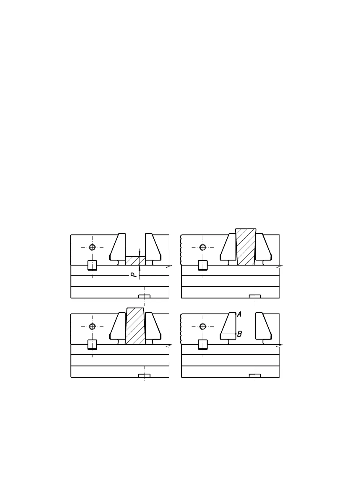
Inadmissible shape, thickness and way of clamping workpieces in vise jaws
presented in Fig. 9 are inadmissible. The workpieces should be clamped at the A-B
section of clamping insert (Fig. 11). The thickness of clamped workpieces (“P”
dimension as in Fig. 11) should not be less then 1/3 h (the “h” values as presented
in Fig. 3).
Fig. 11. Inadmissible shape of workpiece.