6 KB-570-1 RUS
ST-130-2
2
2 Functions
The OLC-D1-S can monitor either the
minimum or the maximum oil level,
depending on its mounting position
and incorporation into the safety
chain. If the minimum and the maxi-
mum oil level should be monitored,
two OLC-D1-S devices must be
installed.
2.1 Monitoring of the minimum
level
Lock out
The compressor is shut off, if the
prism sticks out of the oil longer than
the delay time specified by the circuit.
The OLC-D1-S then opens the output
contact and the circuit locks out elec-
tronically: The control voltage to the
compressor contactor is interrupted.
The red LED at the face side of the
opto-electronic unit lights up (figure 1)
as well as the signal lamp H4.
Reset
The circuit can be manually reset by
pressing the reset button. This reset
button (S4) has to be mounted into
the swich board. (Connection see
sche matic wiring diagram.)
2 Fonctionnement
Le OLC-D1-S peut contrôler soit le
niveau d'huile minimal soit le niveau
d'huile maximal, dépendant de la position
de montage et de l'intégration dans la
chaîne de sécurité. Pour surveiller le
niveau d'huile minimal et maximal en
même temps, deux OLC-D1-S doivent
être installés.
2.1 Contrôle du niveau d'huile minimal
Verrouiller
Le compresseur est arrêté des lors que le
temps pendant lequel le cône de verre
dépasse le niveau d'huile est supérieur à
la la temporisation prédéfinie par le
réglage.
Le OLC-D1-S ouvre alors le contact de
sortie et le circuit se verrouille électroni-
quement: la tension de commande du
con tacteur du compresseur est alors
coupée. La LED rouge sur le côté frontal
de l'unité opto-électronique s'allume (figu-
re 1) et ainsi que la lampe H4.
Déverrouiller
Le circuit peut être remis manuellement
en fonctionnement par la touche de reset.
Cette touche (S4) devra être montée
dans l'armoire électrique. (Raccordement
voir schéma de principe.)
2 Funktionen
Das OLC-D1-S kann entweder das
mini male oder das maximale Ölnive au
über wachen, je nach Montage-Posi ti -
on und Einbettung in die Sicher heits -
kette. Falls sowohl das mini male wie
das maximale Ölnive au über wacht
werden soll, müssen zwei OLC-D1-S
installiert werden.
2.1 Minimale Ölniveau-Überwa-
chung
Verriegeln
Der Verdichter wird abgeschaltet,
wenn der Glas-Kegel länger als die
durch die Schaltung vorgegebene Ver -
zöge rungs zeit aus dem Öl herausragt.
Das OLC-D1-S öffnet dann den Aus -
gangs kon takt und die Schaltung ver-
riegelt elektronisch: Die Steuerspan -
nung zum Verdich ter schütz wird unter-
brochen. Die rote LED auf der Stirn -
seite der opto-elektronischen Ein heit
(Abb. 1) und die Signallampe H4
leuchten.
Entriegeln
Die Schaltung kann über eine Reset-
Taste manuell zurück gesetzt werden.
Diese Reset-Taste (S4) muss im
Schalt schrank montiert werden.
(Anschluss siehe Prinzipschaltbild.)
Abb. 1 Abmessungen und Aufbau Fig. 1 Dimensions and design
Fig. 1 Dimensions et construction
1 Prisma-Einheit
2 Glas-Kegel
3 Dichtung
4 Opto-elektronische Einheit "OLC-D1"
(360° drehbar)
5 Anschlusskabel
6 Schraubkappe
1 Prism unit
2 Glass cone
3 Gasket
4 Opto-electronic unit "OLC-D1"
(360° revolving)
5 Connecting cable
6 Screwing cap
1 Unité prisme
2 Cône en verre
3 Joint
4 Composant opto-électronique "OLC-D1"
(mobile sur 360°)
5 Câble de raccordement
6 Chapeau à visser
• BeigrößerenAchsabständen
Beruhigungsrolle (5) verwenden.
Dies reduziert die Riemen-
schwingungen.
• RiemenscheibeundKupplung
müssen fest sitzen und exakt mit
der Antriebsscheibe, Spannrolle
und Motorachse fluchten (Abb. 2).
- Riemenscheiben / Magnet-
kupplungen mit geringst mög-
lichen Abstand der Spurrillen zum
Verdichterlager verwenden.
- Nebenaggregate nur bei geringem
Drehmomentbedarf über die
Verdichter-Riemenscheibe
antreiben (äußere Spurrillen).
- Maximal zulässige Radialkraft
auf die Verdicherwelle:
3000 N bezogen auf Mitte der
Riemenscheibe.
• Useidlerpulley(5)forgreateraxis
spacing. This reduces the belt
vibrations.
• Pulleyandclutchmustbeseated
firmly and be exactly flush with the
drive wheel, idler pulley and engine
axis (fig. 2).
- Use pulleys / magnetic clutches
with the minimum possible
distance between the grooves and
the compressor bearing.
- Run additional units over
the compressor pulley (outer
grooves) at the minimum torque
requirement only.
- Maximum permissible radial force
on the compressor shaft:
3000 N, referenced from the
centre of the pulley.
• Используйте натяжной шкив (5) при
больших расстояниях между осями.
Он снизит вибрации ремня.
• Шкив и муфта должны сидеть плотно
и расположены точно вровень с
ведущим шкивом, натяжным шкивом
и осью двигателя (рис. 2).
- Используйте шкивы / магнитные
муфты с минимально возможным
расстоянием между канавками и
подшипником компрессора.
- Подключайте дополнительные
устройства на шкив компрессора
(внешние канавки) только с учетом
минимальных требований крутящего
момента.
- Максимальная допустимая радиа-
льная сила на валу компрессора:
3000 N по отношению к центру
шкива.
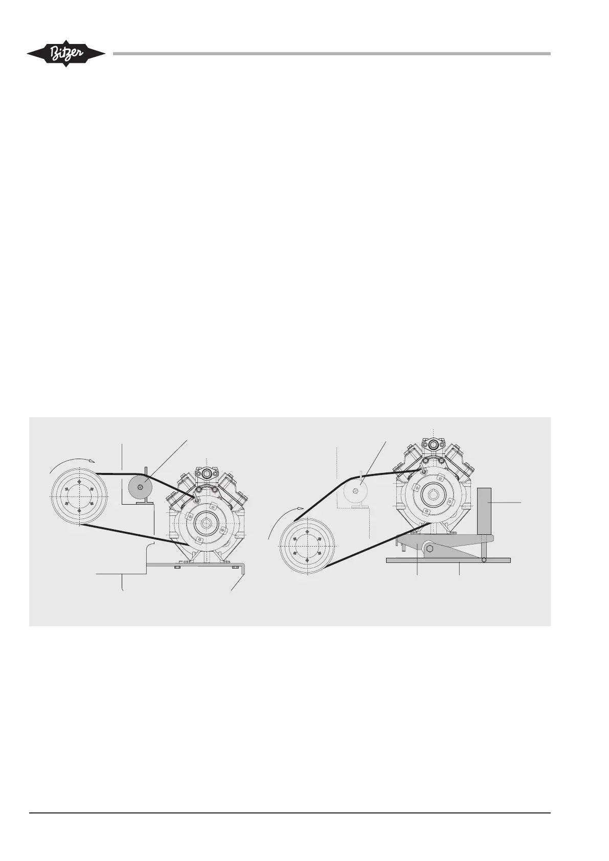
Abb. 1 Einbau-Beispiele
a starrer Anbau am Motor
b Verdichter drehelastisch auf
Chassis montiert
1: Wippe
2: Chassis
3: hydraulischer / pneumatischer
Spannzylinder
4: Riemenspannrolle
(Spannrolle am Trum innen an-
ordnen. Bei Poly-V-Riemen auch
außen möglich.)
5: Beruhigungsrolle
(bei größeren Achsabständen)
Fig. 1 Mounting examples
a Solid mounting at the engine
b Compressor elastically mounted
on a Chassis
1: Rocker
2: Chassis
3: hydraulic / pneumatic tensioning
cylinder
4: Idler pulley
(Arrange pulley at inner side of
span. With poly-V belts outer side
is also possible.)
5: Idler pulley
(for greater axsis spacing)
Рис. 1 Примеры монтажа
a Жесткое крепление к двигателю
b Упругое крепление компрессора на
шасси
1: Балансир
2: Шасси
3: Гидравлический / пневматический
натяжной цилиндр
4: Вспомогательный шкив
(располагайте на внутренней стороне
пролета, при использовании поликлино-
вых ремней можно использовать с
внешней стороны пролета.)
5: Натяжной шкив
(для больших расстояний между осями)
a b
Vereinfachte Darstellung Simplified sketch
Упрощенный эскиз
 Loading...