8 KB-570-1 RUS
ST-130-2
2
2 Functions
The OLC-D1-S can monitor either the
minimum or the maximum oil level,
depending on its mounting position
and incorporation into the safety
chain. If the minimum and the maxi-
mum oil level should be monitored,
two OLC-D1-S devices must be
installed.
2.1 Monitoring of the minimum
level
Lock out
The compressor is shut off, if the
prism sticks out of the oil longer than
the delay time specified by the circuit.
The OLC-D1-S then opens the output
contact and the circuit locks out elec-
tronically: The control voltage to the
compressor contactor is interrupted.
The red LED at the face side of the
opto-electronic unit lights up (figure 1)
as well as the signal lamp H4.
Reset
The circuit can be manually reset by
pressing the reset button. This reset
button (S4) has to be mounted into
the swich board. (Connection see
sche matic wiring diagram.)
2 Fonctionnement
Le OLC-D1-S peut contrôler soit le
niveau d'huile minimal soit le niveau
d'huile maximal, dépendant de la position
de montage et de l'intégration dans la
chaîne de sécurité. Pour surveiller le
niveau d'huile minimal et maximal en
même temps, deux OLC-D1-S doivent
être installés.
2.1 Contrôle du niveau d'huile minimal
Verrouiller
Le compresseur est arrêté des lors que le
temps pendant lequel le cône de verre
dépasse le niveau d'huile est supérieur à
la la temporisation prédéfinie par le
réglage.
Le OLC-D1-S ouvre alors le contact de
sortie et le circuit se verrouille électroni-
quement: la tension de commande du
con tacteur du compresseur est alors
coupée. La LED rouge sur le côté frontal
de l'unité opto-électronique s'allume (figu-
re 1) et ainsi que la lampe H4.
Déverrouiller
Le circuit peut être remis manuellement
en fonctionnement par la touche de reset.
Cette touche (S4) devra être montée
dans l'armoire électrique. (Raccordement
voir schéma de principe.)
2 Funktionen
Das OLC-D1-S kann entweder das
mini male oder das maximale Ölnive au
über wachen, je nach Montage-Posi ti -
on und Einbettung in die Sicher heits -
kette. Falls sowohl das mini male wie
das maximale Ölnive au über wacht
werden soll, müssen zwei OLC-D1-S
installiert werden.
2.1 Minimale Ölniveau-Überwa-
chung
Verriegeln
Der Verdichter wird abgeschaltet,
wenn der Glas-Kegel länger als die
durch die Schaltung vorgegebene Ver -
zöge rungs zeit aus dem Öl herausragt.
Das OLC-D1-S öffnet dann den Aus -
gangs kon takt und die Schaltung ver-
riegelt elektronisch: Die Steuerspan -
nung zum Verdich ter schütz wird unter-
brochen. Die rote LED auf der Stirn -
seite der opto-elektronischen Ein heit
(Abb. 1) und die Signallampe H4
leuchten.
Entriegeln
Die Schaltung kann über eine Reset-
Taste manuell zurück gesetzt werden.
Diese Reset-Taste (S4) muss im
Schalt schrank montiert werden.
(Anschluss siehe Prinzipschaltbild.)
Abb. 1 Abmessungen und Aufbau Fig. 1 Dimensions and design
Fig. 1 Dimensions et construction
1 Prisma-Einheit
2 Glas-Kegel
3 Dichtung
4 Opto-elektronische Einheit "OLC-D1"
(360° drehbar)
5 Anschlusskabel
6 Schraubkappe
1 Prism unit
2 Glass cone
3 Gasket
4 Opto-electronic unit "OLC-D1"
(360° revolving)
5 Connecting cable
6 Screwing cap
1 Unité prisme
2 Cône en verre
3 Joint
4 Composant opto-électronique "OLC-D1"
(mobile sur 360°)
5 Câble de raccordement
6 Chapeau à visser
3.3 Elektromagnet-Kupplung
einbauen
Achtung!
Schrauben und Muttern mit vor-
geschriebenen Drehmomenten
anziehen (siehe Kapitel 8.1).
Achtung!
Nur von BITZER zugelassene
Kupplungen verwenden.
Einbau am Beispiel der Kupplung
LINNIG LA18.060Y (Abb. 4):
Montage des Magneten (2):
• Magnet(2)aufdieWelleschieben
und Aussparung an die richtige
Position drehen.
• Magnet(2)mit4Schrauben(3)
M6x16 an den Verdichter schrau-
ben (Anzugsmoment 10 Nm).
• Kabelsoanschließen,dasses
nicht mit heißen Teilen in Berührung
kommt (t
max
= 105°C).
Dabei muss nicht auf die Polung
geachtet werden.
Montage der Riemenscheibe (1):
• Riemenscheibe(1)aufdenMag-
neten (2) aufschieben und Siche-
rungsring (5) in die Nut einrasten.
!
Warnung!
Sicherungsring (5) steht unter
mechanischer Spannung!
Schwere Verletzungen möglich.
Schutzbrille tragen!
3.3 Installing the electro-magnetic
clutch
Attention!
Tighten bolts and nuts to
the specified torques (see
chapter 8.1).
Attention!
Use only BITZER-approved
clutches.
Installation example for LINNIG clutch
LA18.060Y (fig. 4):
Mounting the magnet (2):
• Slidemagnet(2)ontoshaftandturn
groove into right position.
• Screwmagnet(2)ontocompressor
with 4 screws (3) M6x16 (tightening
torque 10 Nm).
• Connectcableandkeepawayfrom
hot parts (t
max
= 105°C).
Polarity is irrelevant here.
Mounting the pulley (1):
• Slidepulley(1)ontomagnet(2)and
lock in retaining ring (5).
!
Warning!
Retaining ring (5) is under
tension!
Serious injuries are possible.
Wear safety goggles!
3.3 Установка электромагнитной
муфты
Внимание!
Затяните болты и гайки с указанными
моментами (см. раздел 8.1).
Внимание!
Используйте только одобренные
BITZER муфты.
Пример монтажа муфты Linnig LA18.060Y
(рис. 4):
Монтаж магнита (2):
• Насадите магнит (2) на вал и
поверните в правильное положение
под паз.
• С помощью четырех винтов (3) M6x16
привинтите магнит (2) на компрессор
(момент затяжки 10 Нм).
• Подключите кабель так, чтобы он
не соприкасался с горячими частями
(T
макс.
= 105°C).
Полярность не имеет значения.
Монтаж шкива (1):
• Надвиньте шкив (1) на магнит (2) и
зафиксируйте стопорным кольцом (5).
!
Предупреждение!
Стопорное кольцо (5) механически
напряжено!
Возможны серьезные травмы.
Оденьте защитные очки!
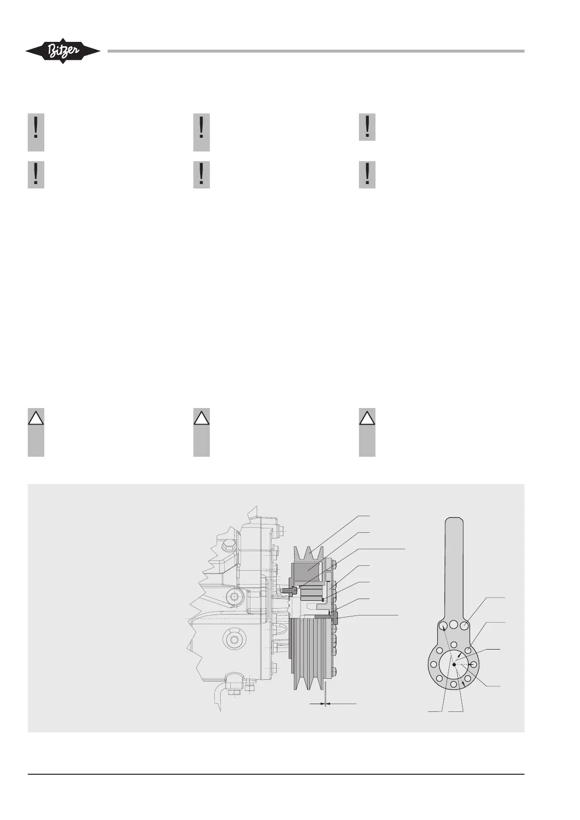
Abb. 4 Elektromagnet-Kupplung und
Ringlochschlüssel
Fig. 4 Electro-magnetic clutch and ring
hole type wrench
Рис. 4 Электромагнитная муфта и ключ с
кольцевыми отверстиями
1 Riemenscheibe
2 Magnet
3 Befestigungsschrauben
4 Ankerscheibe
5 Sicherungsring
6 Einstellscheiben
7 Zentrale Befestigungsschraube
1 Pulley
2 Magnet
3 Fixating screws
4 Armature disc
5 Retaining ring
6 Adjusting washers
7 Central fixing screw
1 Шкив
2 Магнит
3 Крепежные болты
4 Анкерная плита
5 Стопорное кольцо
6 Регулировочные шайбы
7 Центральный крепежный болт
 Loading...