9KB-570-1 RUS
ST-130-2
3
2.2 Maximale Ölniveau-Überwa-
chung
Elektrischer An schluss und Einbin -
dung in die Steue rungs logik sind von
der Konzeption der jeweiligen Anlage
abhängig.
So kann beispielsweise bei einer
Anlagenkonzeption mit überflutetem
Verdampfer ein Magnetventil in der
Ölleitung je nach Ölniveau im Verdich -
ter angesteuert werden. Ebenso ist
die Regelung einer Ölumspeisung im
Parallelver bund möglich.
2.3 Technische Daten
2.2 Monitoring of the maximum
level
The electrical connection and its inte-
gration into the control logic depend
on the design of the particular system.
Thus, for example, in an installation
with flooded evaporator, a solenoid
valve in the oil line can be activated,
depending on the oil level in the com-
pressor. Likewise, the oil circulation
can also be controlled in parallel.
2.3 Technical data
2.2 Contrôle du niveau d'huile maxi-
mal
Le raccordement électrique et l'incorpora-
tion à la logique de commande dépen-
dent de la conception de l'installation en
question.
Il est ainsi possible, par exemple dans le
cas d'une conception d'installation avec
évaporateur noyé, de commander une
vanne magnétique dans la conduite d'hui-
le, suivant le niveau d'huile dans le com-
presseur. La régulation d'un transfert
d'huile dans des compresseurs en
parallèle est également possible.
2.3 Données tech ni ques
Anschluss-Spannung Supply volt age Tension d'alimentation 230 V AC ± 10%
Netzfrequenz Supply frequency Fréquence du réseau 50 / 60 Hz
Verzögerungszeit (integriert) Delay time (integrated) Temporisation (integré) 5 s ± 2 s
Vorsicherung für Gerät Fusing for device and Fusible pour appareil et
und Schaltkontakte switch contacts contacts de commutation
Maximal zulässiger Druck Maximum allowable pressure Pression maximale admissible
Anschlusskabel Connecting cable Câble de raccordement
Kältemaschinenöle Refrigeration compressor oil Huiles pour machines frigorifiques alle / all / toutes
Kältemittel Refrigerants Fluides frigorigènes
Schutzart (montiert) Enclosure class (mounted) Classe de protection (monté) IP54
Zulässige Umgebungstemperatur Allowable ambient temperature Température ambiante admissible -30 .. +60°C
Gewicht Weight Poids 390 g
Opto-elektronische Einheit wird als
OLC-D1 ausgeliefert (siehe Seite 2,
Abbildung 1, Position 4)
andere Spannungen auf Anfrage,
auch mit UL-Abnahme erhältlich
Kabel sind farbkodiert
Opto-electronic unit is delivered as
OLC-D1 (see page 2, figure 1, pos. 4)
other voltages upon request, also
available with UL approval
Cables are color coded
Le composant opto-électronique est livrée
comme OLC-D1 (voir page 2, figure 1,
position 4)
d'autres types de tension sur demande,
aussi avec contrôle UL
Câbles avec code couleur
5 x AWG 20 (0,75 mm
2
)
L = 2 m
HFKW, (H)FCKW
HFC, (H)CFC
Relais-Ausgänge: Relay output: Sorties de relais:
Schaltspannung Switching voltage Tension de commutation max. 240 V AC
Schaltstrom Switching current Intensité de commutation max. 2,5 A
Schaltleistung Switching capacity Puissance de commutation max. 300 VA
max. 4 A
Maximale Öltemperatur Maximum oil temperature Température d'huile maximale 120°C
33 bar (-20°C .. -10°C)
45 bar (-10°C .. 120°C)
Geräte-Typ Device type Type de dispositif OLC-D1-S
Montage der Ankerscheibe (4) und
Justieren des Luftspalts:
• SchraubeM10(7)durchdie
zentrale Bohrung der Ankerscheibe
(4) stecken. Alle beiliegenden
Einstellscheiben in der verzahnten
Bohrung auf die Schraube
schieben. Ankerscheibe (4) mit
verzahnter Nabe auf die verzahnte
Welle stecken. Schraube M10 (7)
handfest anziehen.
• MitFühlerlehreLuftspaltzwischen
Ankerscheibe (4) und Riemen-
scheibe (1) an 3 Stellen am Umfang
messen. Der Luftspalt muss an
allem Messstellen gleich sein und
zwischen 0,4 und 0,7 mm liegen.
Bei Bedarf Ankerscheibe (4)
demontieren und entsprechend
viele Einstellscheiben entfernen.
Die dünnen Einstellscheiben sind
0,25 mm dick, die dicken 0,5 mm.
Überzählige Scheiben werden nicht
benötigt. Schraube M10 (7) anzie-
hen (Anzugsmoment 49 Nm). Dazu
mit speziellem Ringlochschlüssel
(Abb. 4) gegenhalten.
Achtung!
Riemenscheibe muss sich von
Hand drehen lassen, ohne am
Magnet zu schleifen!
Anleitungen für den Einbau anderer
Kupplungen auf Anfrage.
3.4 Absperrventile
Die Absperrventile können gedreht und
an unterschiedlichen Stellen montiert
sein (Anschlüsse siehe Seiten 12, 13).
Mounting the armature disc (4) and
adjusting the gap:
• PutscrewM10(7)intocentrebore
of the armature disc (4). Slide all
included adjusting washers through
the teethed bor onto the screw.
Slide armature disc (4) with teethed
hub onto teethed shaft. Fasten
screw M10 (7) hand-tight.
• Usefeelergaugetomeasure
gap between armature disc (4)
and pulley (1) at 3 points at the
circumference. The gap must be
identical at all measuring points
and lie bewteen 0.4 and 0.7 mm.
If necessary dismantle armature
disc (4) and remove as many
adjusting washers as needed.
The thin adjusting washers are
0.25 mm thick, the thick ones
0.5 mm. Redundant washers are
not needed. Tighten screw M10 (7)
(tightening torque 49 Nm).
Use special ring hole type wrench
(fig. 4) to counter.
Attention!
You must be able to turn the
pulley by hand without it rubbing
against the magnet!
Instructions for the installation of other
clutches upon request.
3.4 Shut-offvalves
The shut-off valves can be rotated
and mounted in various positions (for
connections, see pages 12, 13).
Монтаж анкерной плиты (4) и
регулировка зазора:
• Вставьте болт M10 (7) в центральное
отверстие анкерной плиты (4).
Установите все имеющиеся
регулировочные шайбы внутрь
зубчатой втулки на болт. Установите
анкерный диск (4) с зубчатой втулкой
на зубчатый вал. Затяните болт M10
(7) от руки.
• Используйте щуп для измерения
зазора между анкерным диском (4) и
шкивом (1) в 3 точках по окружности.
Значения зазоров должны быть
одинаковыми во всех точках измере-
ния и лежать между 0,4 и 0,7 мм.
При необходимости демонтировать
анкерный диск (4) и удалить столько
регулировочных шайб сколько
необходимо. Толщина тонких
регулировочных шайб 0,25 мм, толстых
0,5 мм.
Резервные шайбы не нужны. Затяните
винт M10 (7) (момент затяжки 49 Нм).
Используйте специальный ключ с
кольцевыми отверстиями (рис. 4), для
удержания.
Внимание!
Шкив должен проворачиваться
вручную, без трения о магнит!
Инструкции для установки других муфт
по запросу.
3.4 Запорные клапаны
Запорные клапаны могут быть повернуты
и установлены в различных положениях
(варианты соединений, см. стр. 12, 13).
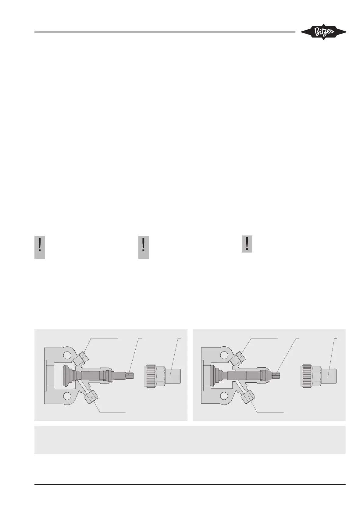
1 Verschlusskappe
2 Spindel
3 Service-Anschluss (absperrbar)
4 Mess-Anschluss
1 Sealing cap
2 Spindle
3 Service connection (can be shut-off)
4 Measurement connection
1 Уплотнительный колпачок
2 Шпиндель
3 Сервисное присоединение (может перекрываться)
4 Присоединение для замеров
Abb. 5 Offenes Absperrventil (Betriebsstellung)
Fig. 5 Open shut-off valve (operating position)
Рис. 5 Открытый запорный клапан (рабочее положение)
Abb. 6 Geschlossenes Absperrventil
Fig. 6 Closed shut-off valve
Рис. 6 Закрытый запорный клапан
 Loading...