CT-110-26
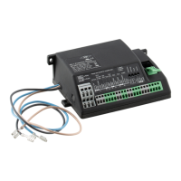
* For the HS.53 and CSHP compressors, the SE-i1 is
exclusively delivered as a separate basic sensor kit
(part number 347 050 02). It must be installed, wired
and connected in the system's switch cabinet!
Use of the SE-i1 in combination with refrigerants of the
A3 (e.g. propane) and A2 safety groups presents a
DANGER
risk of explosion!
The provided protection device contains ignition
sources capable of igniting propane and refri-
gerants of the A3 and A2 safety groups. Install
the protection device outside the hazardous
zone, for example in a tight switch cabinet.
➀ Completion sensor kit
HS.64 .. HS.85, CS.65 .. CS.95:
If the SE-i1 was ordered ex factory with a basic sensor
kit, it can be retrofitted with the completion sensor kit.
Afterwards, all protective and monitoring functions of
the device can be activated and fully used. For this, all
components of the completion sensor kit must be
mounted on the compressor, wired and configured us-
ing the BEST SOFTWARE (see chapter Mounting and
activation of the completion sensor kit, page 8).
When ordering the full sensor kit for the compressors
HS.64 .. HS.85 And CS.65 .. CS.95, all components of
the completion sensor kit are already installed and
electrically connected to the compressor. The comple-
tion sensor kit is not available for CSHP compressors.
The completion sensor kit (HS.64 .. HS.85 And CS.65 ..
CS.95, part number 347 050 03) consists of the follow-
ing components:
• Low pressure and high pressure transmitters with
connecting cables.
• T-pieces for connecting the pressure transmitters to
the high pressure and low pressure connection of
the compressor.
• Discharge gas temperature and oil temperature
sensor (NTC) incl. connecting cable.
• All cable bushings M25x1.5, M20x1.5, M16x1.5 with
hexagon nuts for the terminal box of the compressor.
Mounting and electrical connection, see chapter Mount-
ing and activation of the completion sensor kit, page
8 and see chapter Electrical connection, page 14.
② Optional temperature sensor
For example, for measurements of the suction gas, li-
quid or ambient temperature. Is considered during the
data log.
• Temperature sensor with screw-in thread (part num-
ber 34704101) + cable with plug (part number
34703301).
– 1/8-27 NPTF thread
– Measuring range: -40°C .. +125°C
• Temperature sensor to be placed on the pipe sur-
face (part number 34703301).
– for measurements of the suction gas temperature
on the pipe surface or measurements of the ambi-
ent temperature.
– Measuring range: -30°C .. +105°C
– Enclosure class: IP65
– Cable length: 5 m
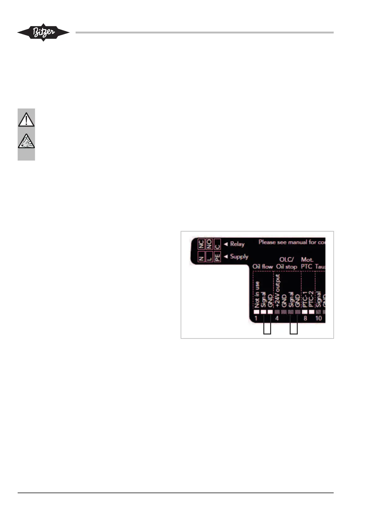
③ Unused oil monitoring inputs
With the setting "SE-C1 Replacement" or "SE-C2 Re-
placement", unused oil monitoring inputs must be deac-
tivated by means of bridges. They must be set between
the following terminals.
Fig.1: Bridge to deactivate the oil monitoring inputs