Chapter 2
Controls and Indicators
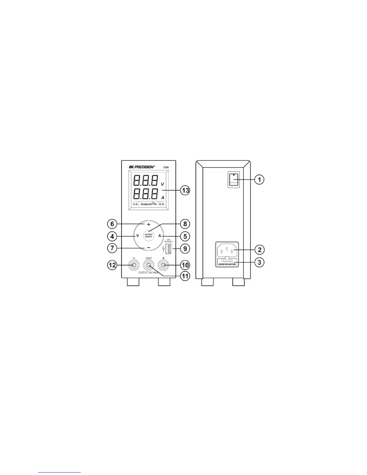
Figure 2.1: Front Panel
1. Power Switch:
Turns the power supply on-o, when it is on the
front display lights up
2. AC Input Socket with Fuse
3. Concealed Fuse box ( please open the cover to get
to the fuse)
4. V: Output Voltage Seing keypad
5. A: Output Current Seing keypad
6. “+” ascend Seing keypad.
Press to ascend the numerical values
7. “-” descend Seing keypad.
Press to descend the numerical values
8. Output On/O push buon.
9. USB Output Socket
Standard USB DC power 5V, 400mA
To charge or to power portables and cell phones
10. Output Terminal Positive (+) Red color
11. GND Terminal (:) Green color
Chassis ground terminal, normally this is to be
short to (+) or (-) as required by user
12. Output Terminal Negative (-) Black color
13. LCD Display panel showing:
3 digit voltage, current meter, (CV) constant
voltage mode, (CC) constant current mode,
Output Terminal on/o state
2