6
ENGLISH
(Original instructions)
● Children shall not play with the appliance. Cleaning and user
maintenance shall not be made by children without supervision.
Residual risks
Additional residual risks may arise when using the tool which
may not be included in the enclosed safety warnings. These
risks can arise from misuse, prolonged use etc.
Even with the application of the relevant safety regulations and
the implementation of safety devices, certain residual risks can
not be avoided. These include:
● Injuries caused by touching any rotating/moving parts.
● Injuries caused when changing any parts, blades
or accessories.
● Injuries caused by prolonged use of a tool. When using any
tool for prolonged periods ensure you take regular breaks.
● Impairment of hearing.
● Health hazards caused by breathing dust developed when
using your tool (example:- working with wood, especially
oak, beech and MDF.)
Vibration
The declared vibration emission values stated in the technical
data and the declaration of conformity have been measured in
accordance with a standard test method provided by EN62841
and may be used for comparing one tool with another. The
declared vibration emission value may also be used in a
preliminary assessment of exposure.
@
Warning! The vibration emission value during actual
use of the power tool can differ from the declared value
depending on the ways in which the tool is used. The
vibration level may increase above the level stated.
When assessing vibration exposure to determine safety
measures required by 2002/44/EC to protect persons regularly
using power tools in employment, an estimation of vibration
exposure should consider, the actual conditions of use and the
way the tool is used, including taking account of all parts of the
operating cycle such as the times when the tool is switched off
and when it is running idle in addition to the trigger time.
Labels on tool
The following pictograms are shown on the tool along with the
date code:
a
Warning! To reduce the risk of injury, the user
must read the instruction manual.
Electrical safety
i
This tool is double insulated; therefore no earth wire
is required. Always check that the power supply
corresponds to the voltage on the rating plate.
uIf the supply cord is damaged, it must be replaced by the
manufacturer or an authorised BLACK+DECKER Service
Centre in order to avoid a hazard.
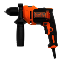
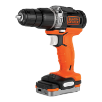
1. Variable speed switch
2. Lock on button
3. Forward/reverse switch
4. Drilling mode selector
5. Chuck
6. Chuck lock
7. Side handle
Assembly
Warning! Before assembly, make sure that the tool is
switched off and unplugged.
Fitting the side handle (g. A)
uTurn the grip counterclockwise until you can slide the side
handle (7) onto the front of the tool.
uRotate the side handle into the desired position.
uTighten the side handle by turning the grip clockwise.
Fitting an accessory (g. B)
uPress the chuck lock (6)
uOpen the chuck by turning the sleeve (5) counterclockwise.
uInsert the bit shaft (8) into the chuck.
uTighten the chuck by turning the sleeve clockwise.
Use
Warning! Let the tool work at its own pace. Do not overload.
Warning! Before drilling into walls, oors or ceilings, check for
the location of wiring and pipes.
Switching on and off (g. C)
uTo switch the tool on, press the variable speed switch (1).
The tool speed depends on how far you press the switch.
uFor continuous operation, press the lock-on button (2) and
release the variable speed switch.
This option does not work in reverse rotation.
uTo switch the tool off, release the variable speed switch.
To switch the tool off when in continuous operation, press
the variable speed switch once more and release it.
Always hold the tool as shown in gure C.
Selecting the direction of rotation (g. D)
For drilling and tightening screws, use forward (clockwise)
rotation. For loosening screws or removing a jammed drill bit,
use reverse (counterclockwise) rotation.
uTo select forward rotation, push the forward/reverse slider
(3) to the left.
uTo select reverse rotation, push the forward/reverse slider
to the right.
Warning! Never change the direction of rotation while the
motor is running.
Selecting the drilling mode (g. E)
uFor Impact drilling in masonry and concrete, set the
drilling mode selector (4) to the
q
position.