• /_ WARNING: When usingelectrictools,basicsafetyprecautionsshouldalwaysbe followedtoreducerisk
of fire,electricshock,and personalinjury,includingthefoflowing:
• Do not incineratethe batteryevenif it is severelydamagedor iscompletelywornout.Thebattery can
explodein a fire.Checkwithlocal codesforpossiblespecialdisposalinstructions.
• Ifanyleakageoflige[d fromthebattery cellsoccurs,discontinueuseimmediatelyandreturnthebattery to
yourlocal Black& DeckerServiceCenteror authorizedservicefoci[ity.
• Neverattemptto openthebatteryfor anyreason.Iftheplastichousingof thebattery breaksorcracks,
immediatelydiscontinueuseand do nat recharge.
• Donot chargeapplianceinrainor inwetlocations.
• Useonlythefollowing_pe andsizebattery:Black& Decker244373 - 12_
• UseonlyBlackandDecker12V charger244374.
• Exercisecareinband_ingbatteriesin_rdernattoshortthebatterywithconductingmateria]ssuchasrings_
braceletsand keys.Thebatteryor conductormayoverheatand causeburns.
• Donot openormutilatethebattery. Releasedelectrolyteiscorrosiveand maycausedamagetotheeyesor
skin.Itmaybetoxicif swaflowed.
• Ifthe batterycasecracksdueto a foil or otherimpactandtheelectrolytegelleaksout,wipeit upwitha
cloth,neutrafizetheacidwithany alkalinesubstancesuchas ammoniasolutionof baking soda.Ifthe
electrolytegetson yourskin,immediatelyflushwithwaterand consulta doctor.
• Donatusebatteryforanythieg_therthanwiththispraduct_r_therdesigeak_=dB_ack&Deckerpreduct.
• Z_ WARNING: The guard mustalways beon the tool to protectthe user.
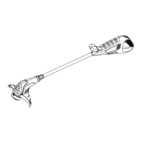
UNITASSEMBLY
Layouttheunffasshowninfigure2. Removethe nutand boltfrom theuppersection(leftportionof Figure2).
Slidethebottomportionintotheupperportionasindicated.Thetwohakes shouldsnaptogether.Re-insertthe
nutandbolttothe uppersection,andtightenbolt.Theunitshouldnowbe rigidlysecured.
GUARDASSEMBLY
Removethescrew from theguard and insertthe guard intotheslot(markedby arrows)inthe trimmerheadas
shownin Figure3. Ensuretileguard isfullyinserted.Re-insertthe screwthrough thetrimmerheadand into
theguard andtightenas shownin figure 4.
NEVEROPERATETHETOOLWITHOUTTHEGUARDPROPERLYIN PLACE.Useof the unitwith out having
installedthe guard will causethe motorto overheat,andvoid the warranty.
BA'rrERY
THELEADACIDBAITERYFORYOURTRIMMERISONLYPARTIALLYCHARGEDATTHEFACTORY.BEFORE
USINGYOURTRIMMER,THEBAITERYMUSTBECHARGEDFORA MINIMUM OF24 HOURS.
• If the battery casecracksdue toa foil or other impact andthe electrolytegel leaksout, wipe it upwith a
cloth, neutralizetheacid with any alkafine substancesuchasammonia solutionor baking soda.If the
electrolytegetson your skin, immediatelyflushwith waterand consulta doctor.
• Yourtrimmer isequippedwith a chargerbracketthat may be mountedfirmly to a wall in your garage,
shedor similar building. (HaVre for hanging the bracketis includedinthe plasticbag packedwith the
trimmen)Chargingyour battery inthis bracketisvery convenientbecauseit hangsthetool up, out ofthe
way and ensuresa good, solid contact betweenthe chargingterminals.
MOUNTINGTHECHARGERBRACKET
1. If youintendto mount,thecharger bracketon a wall, follow the instructionslistedbelow.
2. Removethetwo screwsand plasticanchorsfromtheplasticbag.
3. Usethecharger bracketto markthe locationsof theholesrequired.Besureto mountthe brackethigh
enoughsothat the trimmercan hangfieely fromit;about4 feet(I .2m) fromthe floor:
4. Drilla .250" (6 mm)diameterhole at eachmarked location.
5. Inserttheplasticanchorsintotheholesand insertoneof the screwsin eachone.Tightenthescrewsuntil
the headsare abovethe anchorsjustenoughsothat thecharger bracketwillfit betweentheanchorand
the screwhead.
6. Placethe chargerbracketon thewall narrow end up)and makesure that the powercord ispositioned
inthe sidesat. Pressthe charger bracketoverthe screwheadsand sideit down unti itsitsfirmly onthe
SCI_'%WS.
7. Firmlytightenboth screws.
LEDINDICATORLIGHT
Theunitisequipped with a red LEDcharging indicator light, locatedon the upperleft sideof the unit
(Figure 1).The indicatorlight will comeon when the unitisproperly connectedtothecharging base and the
power plug is insertedintothe electricaloutlet. The lightwill remainon, solong asthe unit ispraperly
connectedto the poweredchargingbase. It is recommendedto storethe unit on thecharger during the
growing season,with thecharger pluggedin, to havethe batterychargedfor the nextuse.
TOCHARGEYOURRAI"I'ERY,FOLLOWTHESTEPSBELOW
1. Installthe trimmerontothe charger bracketbypositioningthe handlecavity, shownin Figure7 over the
hookof the charger bracket.
2. Rotatethe trimmerdown, keepingthehook engagedwiththe handlecavity,and positionthe chargeport
overthe bracket'schargepin (figure7).
3. Plugthe charcjerintoany standard 120 volt,60Hz outlet.Chargingwillbe automaticallycontrolleduntil
you removethetrimmerfromthe bracket.
4. Itisrecommendedthat the trimmerbe lefton charge,durinqtheflrowieg season.Forwinteror other
extendedperiodsof storage,it is recommendedthat the unlitbe f[tlly charged prior to storage.
3. Removethe spoolfrom thetooland removeand discardall lineon spook
4. ChooseeitherOPTION1 or OPTION2 belowfor spoolor line replacement.
5. Inserttheline endthroughthe eyeletinthe spool hub,asshownin figure9. Ensurethe spring isin place
underthe spool.Pulltheline throughthe holeto tightentensionwhileplacing the spooldown intothe
hub, asshownin Figure9.
6. PressthespooldownGENTLYon the springand rotate ituntilyou feel it drop intoplace.Takecare to
keeptheline frombecomingtrappedunder the spcoh
7. Snapthehubcapback onholdr the tool in thetrimmingposition,and tornthetoolon. Ina fewseconds
or lessyou'llhearthenylonline beingcutto the properlength; ifnotbumpthefeedhead gentlyon the
groundto releasea freshlengthof line.
OPTION1: ACCESSORYREPLACEMENTSPOOL
UsereplacementspoolModel No. RS-136.
OPTION2: REWINDINGSPOOLUSINGBULKLINE
Bulklinefor your _mmer is availableat extracostfromyour local dealeror Black& DeckerService
Center.Toinstal]bulk line, follow thestepsbelow.(Use0.065" diameterroundLINEONLY).
1. Insertone endof the bulkline intothehole in the spoolas shownin Figure10 aboutI/8" (3.2ram).
2. Snuglyandevenlywindthe bulkline ontothespoolin thedirectionofthearrowonthe spool, (figure11),
untilthefine buildsupto the notchesinthe spoolrim.DOnot overfillspool.Thespoolholdsabout20 feet
(6 m)of line.
CLEANING AND STORAGE
1. Keeptheair intakeslots(Figure51cleanto avoid overheating.
2. Yourtrimmerline can dry outovertime.Tokeepyour line intop condition,staresporepre-woundspools
or bulk finein a plastic,sealablebagwitha tablespoonof ,,vale,:
3. Plasticportsmaybe cleanedby usinga mild soapand a damprag.
4. DO NOT immersetoolin wateror squirtitwitha hose. DO NOT allowany liquid to get insideit.
5. Donotstarethetoo]onor adjacentto fertilizers, gasoline,orotherchemicals.
6. DO NOT dean witha pressurewasher:
7. Theline cufferontheedgeoftheguard candull overtime. Itis recommendedyouperiodically
touch-upthe sharpnessof the bladewitha file.
ACCESSORIES
• Reloadnylon line eitherbulkor prewound replacementspool as shown in this manual. Use
Back & DeckerRepacementspoo, Mode No. RS-136.
• USEONLY0.065" 1.65 ram)diameterROUNDmonofllamenttrimmerline. Do not useheavier
gauge line,as it will overload the motor and causeoverheating.Theunit functionsproperlyonly with
0.065" diameterROUND monofilamentline.Thisline is avatla_01eat your local dealeror Black& Decker
ServiceCenter.
Z_WARNING: Theuseof any accessorynot soldby Black& Deckerfor usewith this tool could be
hazardous.
IMPORTANT:ToassureproductSAFETYAND REUABILITY,repairs shouldbe performed by a Black& Decker
or other qualified serviceorganization, usingonly identicalreplacementports.
SERVICEINFORMATION
Black& Deckeroffersa full networkofcompony-ownedand authorizedservicelocationsthroughoutNorth
America. All Black& DeckerServiceCentersarestaffedwith trained personneltoprovidecustomerswith
efficient and reliablepowertoolservice.
whether youneedtechnicaladvice,repair,or genuinefactoryreplacementports,contacttheBlack& Decker
location nearestyou.
Tofindyour localservicelocation,referto theyellowpage directory under"Tools_lectric"
orcall: 1-800-54-HOW-TO.
FULLTWO-YEARHOMEUSEWARRANTY
Black& Decker(U.S.)Inc.warrantsthis productfor two yearsagainstanydefectsin materialor
workmanship.Thedefectiveproductwill be replacedor repairedat no cbarge ineitheroftwo ways:
Thefirst,which willresultin exchangesonly,isto returntheproduct tothe retailer fromwhom itwas
purchased(providedthatthestoreisa participating retailer). Returnsshouldbe madewithin thetimeperiod
of theretailer'spolicy for exchanges(usually30 to 90 daysafterthesale). Proofof purchasemay be
required. Pleasecheckwith the retailerfor their specificreturnpolicy regarding returnsthatare beyondthe
timesetfor exchanges.
Thesecondoption is to takeor sendthe produd (prepaid)toa Black& Deckerownedor authorized service
centerfor repair orreplacementatour option. Proofof purchasemay be required.Black& Deckerowned
and authorizedservicecentersare listedunder "Tools-Electric"intheyellow pagesof thephonedirectory.
Thiswarranty doesnotapply toaccessories.Thiswarranty givesyou specificlegalrightsand you mayhave
ather rightswhichvary fromstatetostate.Shouldyou haveanyquestions,contactthemanagerofyour
nearestBlack& DeckerServiceCenter.
Thistoolis notintendedfor commercialuse.
Im rteclby
Black& _ker (U.S.I Inc.,
701 E.JoppaRd.
Towson,MD 2"1"286U.S.A.
See 'Tools-Electric' []
- Yellow Pages -
for Service & Sales
GUIDED'UTILISATION
ModUle CST800
•/_ CAUTION: ALWAYSWEAR EYEPROIECTION.
• Z_ CAUTION: Inspectarea to be trimmedand remove anywire, cord, or string-likec_o_'tswhich couldbecome
entangled in the rotating line or spool Be porticularly carefulto avoid any wire which might
be bent outwardly into the path of the too], suchas barbs at the base of a chain link fence.
• To torn trimmer on, pull back on the lock out button, shown in Figure 1, at the same time, squeeze the
trigger switch. Totam the tool off, release the trigger switch.
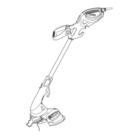
• Angle unit as shown in Figure 5.
• Slowly swing trimmer side-ta-side as shown in Figure 6.
CUTrlNGUNE
UNEFEEDING
Your_mmer onlyuses.065" (1.65 mm)diameter,ROUNDnylonline to cut grassandweedsquicklyand
easily.During use,the tipof the nylonlinewill becomefrayed and worn.Gently bumpthe feedheadof the
trimmeron t_egroundto releasea freshlengthof line.Cuffing line willwear fosterand requiremore feeding
if the cuttingisdone along sidewalksor other abrasivesurfacesor heavierweedsare being cut.
CLEARINGJAMSAND TANGLEDUNES
Fromtimeto time,especiallywhencutting thick or stalkyweeds,the line feeding hub may becomeclogged
with sap orothermaterialandtheline willbecome jammedasa result.Toclear the iam, foffowthe steps
listedbelow.
1. Turnthe unitupsidedown.
2. Pressthe releasetabson thelinehub cover andremoveby pulling itstraightoff (Figure8).
3. Liftthe spoolof nylonlineoutof the hubandclear anybrokenline orcutting debrisfromthespoolarea.
(Ifyou plantoreplacethespoolor rewindit,this istheplace to do so, otherwise,moveon.)
4. Unwrapaboutonefoot 30 cm) of line to ensurethatit'sundamaged.If itis okay,rewindit andinsertthe
lineendthrough theeyeletin thespool hub as shownin figure 9. Ensurethespringis in place underthe
spool.Pullthe]ine throughtheholeto maintaintensionwhileplacing thesp:x_ldown intothe hubwith
thearrow up, as shownin figure9.
5. Pressthe spooldown GENTLYonthespringand rotateit untilyoufeel itdrop intoplace.Takecare to
keepthe line frombecomingtrappedunderthespool.
6. Snapthe hubcap back onhold the too]inthe trimming position,andtorn thetoolon. Ina Jewseconds
or lessyou'll hear the nylonfinebeingcuttathe properlength;if notbumpthe feedheadgently on the
groundto initiatea freshlengthof line.
SPOOLOR UNEREPLACEMENT(Use0.065" diameterROUNDllneonly.)
1. Turnthe unit upsidedown.
2. Pressthereleasetabson theline hubcap, asshownin Figure8 and removethecap by pullingit straight
off.
RENSEIGNEMENTSIMPORTANTS
• Char er I'ensemble de lies endant un minimum de 24 heures avant d'utiliser
g P P ,
coupe-bordure, en se servant du chargeur de 12 volts, modele 244374, de
Black & Decker.
• Le protecteur dolt _tre install_ avant d'utiliser le coupe-bordure. Sinon, le moteur
surchauffera et cela annulera la garantie.
I
• Pour actionner le cou_e-bordure ii taut d abord tlrer le bouton de verrouilla,',e en
iv #
I
mode hors tension vers Iarri_re afin de pouvolr actlver la d@tente.
• Lorsdu remplacement du fil, utiliserseulementdu fil ROND de1,65 mm (0,065 po)
de diam&tre. Sinon, I'appareil risque de ne pas fonctionner convenablement.
CONSERVERII PRESENTGUIDEA TITLE DEREFERENCE.
ib' AVERT1SSEMENT:Lorsqu'onutiliseunoutil de iardinage,il fourtouiours respectercertainesr_glesde
s_curit_fondamentalesafinc_eminimiserlosrisquesd'incendie, de secousses
_lectriquesoude blessures,notammentlessuivantes.
Z_ AVERTISSEMENT: Lepreduitg_n_rede ]apoussi_requi pout renfermerdespreduitschimigees.Selon
1'6tatdela Ca]ifornie,cespreduitschimigeespeuventcauserle cancerainsigee
desmalformationscong_nitales,et ilspr6sententd'autres dangersau syst_me
repreductifhumain. Voicidesexemplesde te]spreduitschimiques:
•lescomn,'_s d'en,'_rais"
•les com,-_',_sd'insecticidesd'herbicides etde ,_=sticides"
• I'arsenicet le chromeprovenantde baistrait@.
Afin de minimiserles risques,porter de I'_quipementde s6curi_ apprau_ commedes masques
antipoussi_ressp_cialementconcu pour filtrer lesporticulesmicroscopiques.

 Loading...