877-877-2269 | blackbox.com
Page 12
Chapter 3: Installation
Table 3-1. PoE/PoE+ connector pinout.
RJ-45 Pin Signal CAT5 Cable Color
1 TX_D1+ and PoE White / Orange
2 TX_D1- and PoE Orange
3 RX_D2+ and PoE White / Green
4
PoE +/- 48 V
Blue
5 White / Blue
6 RX-D2- and PoE Green
7
PoE Common
White / Brown
8 Brown
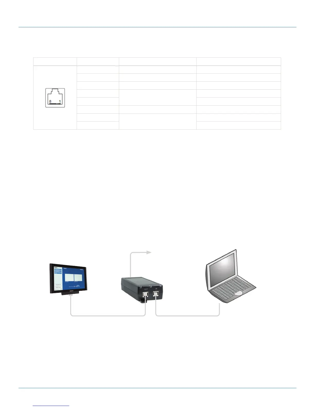
3.3.2 Direct PC Connection
The touch panel models are equipped with PoE power supply (7” models) or PoE+ power supply (12” models). That means
one CATx cable is used for power supply and for data.
Make sure you use:
• PoE Adapter for 7" model
• PoE+ Adapter for 12" model
Follow these steps:
1. Attach one end of an RJ-45 Ethernet straight-through cable to the LAN port on the ControlBridge touch panel and attach
the other end of this cable to the OUT port of a PoE (or PoE+) Adapter.
2. Attach one end of an RJ-45 Ethernet straight-through cable to the IN port of the PoE (or PoE+) Adapter and attach the
other end of this cable to the LAN port of your computer.
3. Attach the power supply to the PoE (PoE+) adapter.
Power supply
PoE Adapter for 7” models
PoE+ Adapter for 12” models
Ethernet cable straight-through
Ethernet cable crossed-over
Figure 3-4. Direction PC connection.
 Loading...