EasyManua.ls Logo

Black Box IC108A User Manual

Black Box IC108A
33 pages
To Next Page IconTo Next Page
Page #1 background imageLoading...
Page #1 background image
CUSTOMER
SUPPORT
INFORMATION
Order toll-free in the U.S.: Call 877-877-BBOX (outside U.S. call 724-746-5500)
FREE technical support 24 hours a day, 7 days a week: Call 724-746-5500 or fax 724-746-0746
Mailing address: Black Box Corporation, 1000 Park Drive, Lawrence, PA 15055-1018
Web site: www.blackbox.com • E-mail: info@blackbox.com
APRIL 2002
IC108A IC109A
IC108C IC109A-R2
IC108AE IC109C
IC109AE
RS-232485/422 Converter Plus
RS-232485/422 Opto-Isolator/Converter
TX RX CD RTS PWR
DCE
DTE
232485/422
OPTO-ISOLATOR/CONVERTER
NORMAL
DLB
RX TX RTS CD
TX RX CD RTS PWR
RX TX RTS CD
DCE
DTE
NORMAL
DLB
232485/422
CONVERTER PLUS

Other manuals for Black Box IC108A

Question and Answer IconNeed help?

Do you have a question about the Black Box IC108A and is the answer not in the manual?

Black Box IC108A Specifications

General IconGeneral
Interface10/100BASE-TX to 100BASE-FX
StandardsIEEE 802.3u
ConnectorsRJ-45, SC
Fiber TypeMultimode
DistanceUp to 2 km
Wavelength1310 nm
Power5V DC
Data Rate100 Mbps
Operating Temperature0°C to 50°C
Power Supply5V DC
Weight200 g

Summary

FCC and IC RFI Statements

Normas Oficiales Mexicanas (NOM) Electrical Safety Statement

Instrucciones de Seguridad

Safety instructions for operating electrical equipment.

Trademarks Used in this Manual

1. Specifications

2. Introduction

3. Installation

3.1 Jumper and Switch Configuration

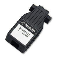
Details jumper and switch settings for configuring the converter.

3.1.1 DTE/DCE Configuration

Configures the RS-232 port as DTE or DCE using a DIP shunt.

3.1.2 & 3.1.3 Ground & Duplex Settings

Configure signal ground and half/full-duplex operation.

3.1.4 CTS Delay

Configures CTS delay for communication link stabilization.

3.1.5 RS-485 Driver Enable

Sets how the RS-485 driver is enabled: by control leads, data, or constantly.

3.1.6 & 3.1.7 Turnaround & Termination Settings

Configures turnaround delay and RS-485 interface termination.

3.1.8 Normal/Loopback Operation

Switches between normal operation and loopback testing of the converter.

3.1.9 RS-485 Interface Line Biased

Enables or disables line bias for fail-safe operation.

3.2 DCE/DTE Configuration

Explains DCE/DTE operation using block diagrams and jumper settings.

3.3 Typical Applications

Describes common use cases and connection examples for the converter.

Sample 4-Wire Multipoint Configuration

Details a sample multipoint setup using an industrial controller and PLCs.

Appendix A: Pinning

Quick Reference: User-Selectable Options

Jumper XW1 & W8 Configuration

DCE/DTE and wire mode settings for jumpers XW1 and W8.

Jumper W15, W5, W9, W17 Settings

RS-485 driver enable and delay settings for jumpers W15, W5, W9, W17.

Jumper W16 & Switch Settings

Turnaround delay, operation modes, termination, and line bias settings.

Terminal Block Pinning (TB1)

Pin assignments for the 4-wire terminal block (TB1).
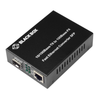
Related product manuals