Max Express Ethernet Switch LB9217A-R2 & Applicable Modules
11
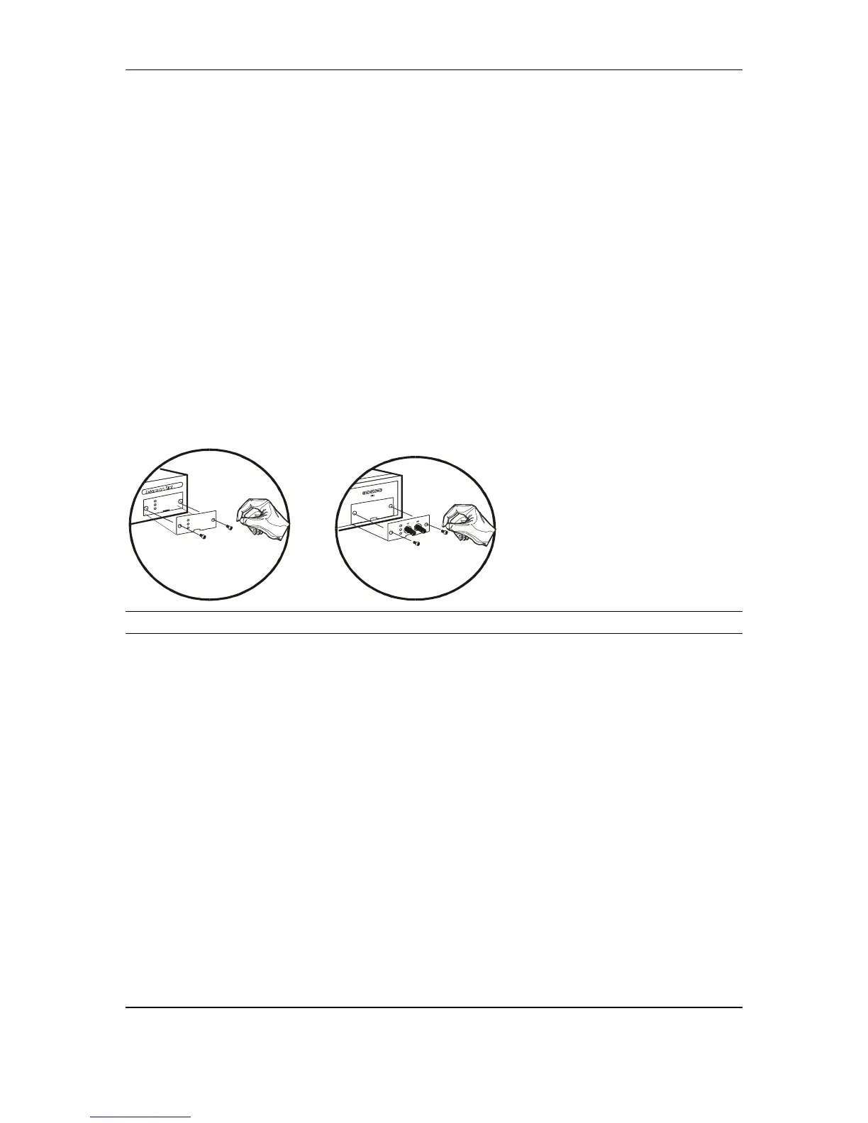
Step by Step Installation for Single Port Module:
LB9220C-ST & LB9220C-SC
1. Remove the module from the static-free container.
2. Unscrew the cover plate(s) from base unit on position C.
3. Remove the plate and keep it for future use if the module needs to be
detached later on. Keep the screws for the installation. Unlike 8-port
module, screws are not attached on single port module.
4. With the power off, slide the module(s) into the desired slot, following the
internal plastic guide rails.
5. Once it is slid in fully, snap in the module to make a proper connection
and fasten the screws that obtained from removing the original plate.
<NOTE> Before you start with any installation, ensure that the power is off.
The module is not hot swappable.
Figure 3: Removal of cover plate Fiber module being installed