5
Illustration Index
Illustration 4.1: Telescopic Rod to mount the search coils and main unit ................................................ 18
Illustration 4.2: Rod Shaft Lock in the locked position ............................................................................. 18
Illustration 4.3: Rod Shaft Lock in the unlocked position ......................................................................... 18
Illustration 4.4: Shows the control unit ready to mount to bracket . ........................................................ 19
Illustration 4.5: Control unit mounted to bracket ..................................................................................... 19
Illustration 4.6: Telescopic Rod end .......................................................................................................... 19
Illustration 4.7: Search Coil mounted to Telescopic Rod .......................................................................... 19
Illustration 4.8: Corner ready for assembly . ............................................................................................. 20
Illustration 4.9: Corner assembled . .......................................................................................................... 20
Illustration 4.10: create a loop in the cable to insert into straight pieces ................................................ 20
Illustration 4.11: Fully assembled coil frame ............................................................................................ 20
Illustration 4.12: Connecting the straps . .................................................................................................. 21
Illustration 4.13: The 150 cm x 150 cm coil can be carried by 1 or 2 people ........................................... 21
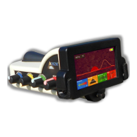
Illustration 5.1: Complete View . ............................................................................................................... 23
Illustration 5.2: Bottom of unit showing the mounting clip . ..................................................................... 23
Illustration 5.3: Rear of unit showing battery and coil connectors . ......................................................... 24
Illustration 5.4: Right side unit controls . .................................................................................................. 24
Illustration 5.5: Main Screen . ................................................................................................................... 25
Illustration 5.6: Left side of the control unit ............................................................................................. 25
Illustration 5.7: Delay Screen . .................................................................................................................. 26
Illustration 5.8: Interference Screen . ....................................................................................................... 26
Illustration 5.9: Threshold Screen . ........................................................................................................... 26
Illustration 5.10: Sensitivity Screen .......................................................................................................... 26
Illustration 5.11: Front of control unit . ..................................................................................................... 27
Illustration 6.1: Procedure for swinging unit from side to side . ............................................................... 30
Illustration 6.2: Example of how to properly pin point a target . .............................................................. 31