13
4.8 The abrasive valve
Between the abrasive storage hopper and the feed spout there is a valve incorporating a permanent magnet in
order to control the abrasive flow towards the blastwheel. Any change in the opening of the magnetic valve
causes the amount of abrasive fed to the blastwheel to change. The change in the abrasive fed can be read
from the ammeter. The valve is hand-operated by the abrasive control cable. This control cable is located on
the control box and can be adjusted so that any quantity of abrasive can be fed to the blastwheel. Optimum
blast cleaning power is reached when the ammeter indicates the operating current. It is not permitted to blast
with a higher current value.
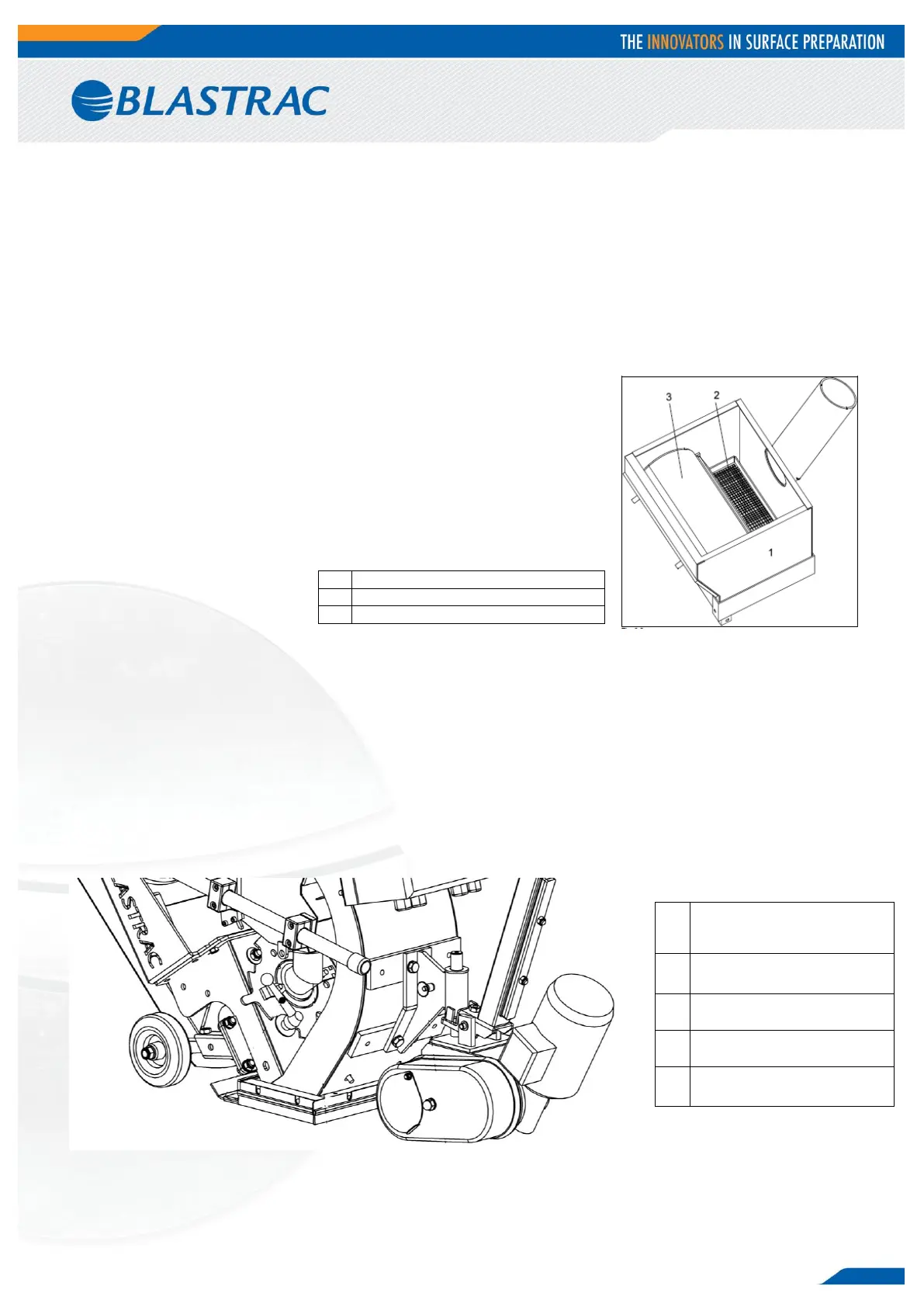
4.9 Separator
The abrasive separator is mounted to the end of the rebound plenum. It
separates the abrasive from contaminants and feeds the cleaned abrasive
back to the abrasive circuit. A wire mesh is fitted to prevent any large
contaminants from getting into the blast wheel. In order to clean the wire
mesh drawer, the separator cover can be removed or the wire mesh drawer
can be removed from the side.
During operation U should check the separator tray every 3 hours for
foreign matter and large contaminants.
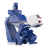
4.10 Abrasive sealing
Magnetic seals are fitted to the front and the sides of the blast housing outlet and are surrounded by brush
seals. At the rear there are two seals sliding over the floor. The seals are employed to seal the blasting area in
a way to avoid leakage of any abrasive.
The correct height adjustment of the magnetic seals (8–10 mm) is very important for optimum functionability
of the machine.
The adjustment is done using the 3 setting screws (one each at the rear wheels and one at the front drive wheel
bracket below the control box).
The height of the brush seals should be maximum 1 mm above the surface. Adjustment is effected through slotted
holes.
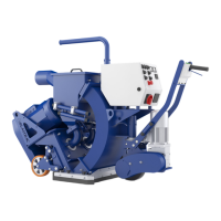
Separator drawer (wire mesh)
Setting screw rear wheel
(quantity: 2)
One on each rear wheel.
Setting screw drive wheel
(quantity: 1)