14
Operation mode is selected during the fan mounting or during the fan
operation from three or five operation modes.
Do not set the DIP switch in any other position except those positions that
are stated in the table 4. Otherwise it may result in the emergency mode
which is confirmed by the light indicator blinking.
In this case disconnect the fan from power supply and set the DIP-switch
into required position in compliance with the table 4.
Calm 150 T
Calm Max 150 T
Calm 150 ST
Calm Max 150 ST
Calm 150 IR
Calm Max 150 IR
ON
1
2
3
4
Operation
mode 1
ON
1
2
3
4
ON
1
2
3
4
ON
1
2
3
4
ON
1
2
3
4
Calm150 H
Calm Max 150 H
Calm 150 SH
Calm Max 150 SH
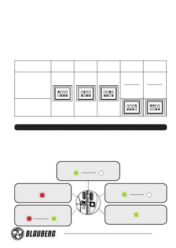
FAN OPERATION MODE INDICATION
The light indicator glows yellow during operation of all the Calm 100,
Calm 125 models as well as Calm 150, Calm Max 150 basic and S models.
The light indicators glows as shown in fig. 27 during operation of the fan
models Calm 150 and Calm Max150 T/ST/H/SH/IR.
Turn-on delay timer is activated
Humidity sensor or
motion sensor is activated
Switch is closed
1 Sek
Green
Red
No signal from sensors or switch
Turn-off delay timer is
activated
Table 4. Operation mode selection
Fig. 27
5 Sek
1 Sek
Operation
mode 2
Operation
mode 3
Operation
mode 4
Operation
mode 5
Red
Green
Green
Green