6
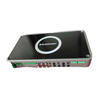
THA 555 PnP
In conclusion, allow us a few words about the topic of
health protection:
During the playback of music in your vehicle, please
consider that continuous sound-pressure levels above
100 dB can lead to permanent damages to the human ear
and even to loss of hearing. Using today's high-perform-
ance systems and loudspeaker confi gurations allows for
reaching sound-pressure levels above 130 dB.
Safety notes
Please observe the following safety notes
during the installation and connection.
- Disconnect the negative pole of the battery! Obser-
ve the safety notes of the vehicle manufacturer.
- When you drill holes, ensure that you do not damage
any vehicle components.
- The cross section of the plus and minus cable may
not be less than 2.5 mm
2
(A.W.G. 13).
- Use cable glands for holes with sharp edges.
- An incorrect installation can result in malfunctions
of the electronic vehicle systems or your car sound
system.
Installation and connection instructions
With respect to accident safety, the THA 555 PnP must
be secured in a professional way.
When selecting the installation location, select a dry
location that offers suffi cient air circulation for cooling
the amplifi er.
The installation surface must be suitable to accept the
accompanying screws and provide a fi rm support.
The amplifi er power cable must be fi tted with a
fuse no more than 30 cm from the battery (see Fig. 2a)
to protect the vehicle battery in case of a short circuit
between power amplifi er and battery. The fuse of the
amplifi er protects only the amplifi er, not the vehicle
battery.
Use loudspeakers with 2-4 Ω impedance (see table or
installation drawing). Observe the maximum power
handling capacity (music output). Do not connect loud-
speakers to earth, use only the referenced terminals.
Application options and loudspeaker connection:
Stereo mode
Max power
Max power
RMS power
RMS power
4 x 110 watt / 4 Ω
4 x 130 watt / 2 Ω
4 x 55 watt / 4 Ω
4 x 65 watt / 2 Ω
Fig. 4
Fig. 4
Bridge mode
Max power
RMS power
2 x 300 watt / 4 Ω
2 x 150 watt / 4 Ω
Fig. 5
Fig. 5
SUB
Max power
RMS power
1 x 400 watt / 4 Ω
1 x 200 watt / 4 Ω
Fig. 5
Fig. 5
RMS power acc. to CEA-2006 ( <1% HD/+14.4 V)
Frequency
response
10 Hz - 30,000 Hz
Signal-to-noise
ratio
> 95 dB @ RMS power
Signal-to-noise
ratio
> 78 dB @ 1 w/ 1 kHz
Distortion factor
(RMS)
< 0.05%
Stability
2 Ω (4 Ω in bridge
mode)
Input sensitivity
0.3 - 8 V
Input sensitivity
Direct AUX IN
0,3 V
Low-pass fi lter
(Low Pass)
50-250 Hz
High-pass fi lter
(High Pass)
10-250 Hz
Bass boost
0 dB to +12 dB
Inputs
6 x cinch/RCA,
4 x HighLevel speaker PnP
2 x Direct Aux inputs, 3.5 mm
stereo
Outputs
2 x loudspeaker,
Dimensions
W x H x D (mm)
356 x 42 x 160 (14"x1,7"x6,3)
Plus / minus connection
- We recommend a minimum cross section of 2.5 mm
2
(A.W.G. 13).
- Route a commercially available positive cable to the
battery and connect it via fuse holder 30 cm from
the battery.
- Use cable glands for holes with sharp edges.
- Securely fasten commercially available minus cables to
a noise-free earth point (chassis screw, chassis metal)
(not to the minus pole of the battery).
- Scrap the contact surfaces of the earth point until
they are bright and grease with graphite grease.
Integrated fuses (Fuse)
The fuses integrated in the amplifi er protect the power
amplifi er and the entire electrical system in case of an
error. If a replacement fuse is used, never bridge fuses
or replace them with a type with higher current.
THA_555_1_16.indd 6THA_555_1_16.indd 6 06.07.2007 10:57:54 Uhr06.07.2007 10:57:54 Uhr
 Loading...