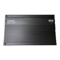
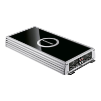
Do you have a question about the Blaupunkt Velocity VA4100 and is the answer not in the manual?
Details 'Thermal-Throttle' protection, installation flexibility, remote gain, and noise isolation features.
Provides critical warnings and precautions before and during the installation process.
Lists essential hand tools and power tools required for amplifier installation.
Details fuse size recommendations based on amplifier power output for safety.
Explains wire gauge requirements for power delivery based on length and power.
Provides recommended speaker wire gauges based on power and wire length.
Covers routing of audio cables, power connections, and grounding.
Allows external adjustment of subwoofer gain while seated in the vehicle.
Covers gain, crossover mode selection, and frequency adjustment for channels.
Details High-Pass and Low-Pass filter settings for frequency management.
Describes RCA inputs and the option for high-level adapter connection.
Connects the amplifier to appropriate impedance speakers, requiring careful polarity.
Located on the amplifier for catastrophic protection; must remain in circuit.
Details +12V battery connection, ground, and the trigger line for amp turn-on.
Indicates power status and protection mode; a short circuit may cause protection.
Describes a 'poor-man's' satellite/subwoofer system using passive components.
Offers an advantage with internal high-pass crossover, protecting front speakers.
Increases rear speaker power for louder sound or complements a subwoofer system.
| Channels | 4 |
|---|---|
| Output Power @ 4 Ohms | 100W x 4 |
| Output Power @ 2 Ohms | 150W x 4 |
| Output Power @ 4 Ohms Bridged | 300W x 2 |
| THD | <0.05% |
| Signal-to-Noise Ratio | >90dB |
| Fuse Rating | 25A x 2 |
| Frequency Response | 10Hz - 45kHz |
| Input Sensitivity | 0.2V - 8V |
| Low Pass Filter | 40Hz - 400Hz |
| Bass Boost | 0dB - 12dB |
