iv
IM0001_L2_R_WMv1.3
Figures
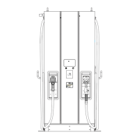
Figure 1 – blink Installations, Typical .......................................................................................... 7
Figure 2 — Shipping Box Contents ............................................................................................ 8
Figure 3 – Hardware Packet Contents ........................................................................................ 9
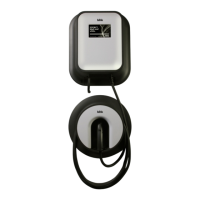
Figure 4 – Charger Housing Assembly and Cord Reel ................................................................ 10
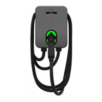
Figure 5 – Charger Assembly Installation .................................................................................. 12
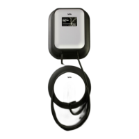
Figure 6 – Cord Reel Installation .............................................................................................. 13
Figure 7 – Cord Reel Cover Installation .................................................................................... 14
Figure 8 – Cord Reel Vehicle Connector ................................................................................... 15
Figure 9 – Housing Cover Removal .......................................................................................... 17
Figure 10 – Supply Circuit Port ................................................................................................ 18
Figure 11 – Service Wiring Terminals ...................................................................................... 18
Figure 12 – Bezel Installation .................................................................................................. 19
Figure 13 – Security Seal ........................................................................................................ 20
Figure 14 – Location of RJ45 (Ethernet) Port .............................................................................. 21
Figure 15 – Closed RJ45 (Ethernet) Port .................................................................................... 21
Figure 16 – Open RJ45 (Ethernet) Port ..................................................................................... 21
 Loading...