Do you have a question about the Blueview BV5000 and is the answer not in the manual?
Lists all components included in the BV5000 package for verification.
Explains how the BV5000 produces 3D point clouds via mechanical scanning.
Provides a quick overview of the process for collecting 3D point cloud data.
Step-by-step instructions for installing the ProScan software.
Specifies the minimum hardware and OS requirements for ProScan.
Instructions for installing Meshlab, a point cloud viewer.
Information about the optional Leica Cyclone software package.
Detailed steps for installing and licensing the Leica Cyclone software.
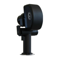
Guides on physically assembling the BV5000 sonar system components.
Details on connecting all hardware components for testing.
Instructions for installing necessary drivers for the Pan & Tilt unit.
Steps to configure the PC's static IP address for system communication.
How to establish a connection between the ProScan software and the BV5000.
Mounting instructions for the Pan & Tilt unit onto various structures.
An annotated overview of the ProScan software interface elements.
Explains how intensity and range data are displayed in the sonar window.
Details the functions accessible via the ProScan software toolbar.
Describes how to use the length measurement tool within ProScan.
Explains the function of range sliders for data acquisition.
Details the controls for playing back recorded sonar data files.
Overview of sonar-specific settings like range threshold and sound velocity.
Procedure for manually calibrating the sonar image for accuracy.
Explains how to control the sonar's pan and tilt movement.
Description of various text boxes providing real-time system status.
Configuration options for setting up single and spherical scans.
How to set up and enable data logging for scans.
Describes the .son file format for intensity data.
Explains the .xyz and .off file formats for 3D point cloud data.
Details the .txt file containing sonar and scan configuration settings.
Overview of the system's ability to reprocess raw scan data.
Step-by-step guide for reprocessing previously saved sonar data.
General troubleshooting for connection problems between sonar and PC.
Specific steps to resolve connection problems with the Pan & Tilt unit.
Troubleshooting steps involving changing USB ports for connectivity.
How to check if the USB COM port is correctly recognized.
Instructions for reinstalling drivers to resolve connection issues.
Guidance on inspecting physical connectors for proper seating and condition.
Steps to verify that the system is receiving adequate power.
Troubleshooting steps specific to the sonar head connection.
Procedure for rebooting the system to resolve network or connection issues.
Steps to troubleshoot and verify network configuration settings.
Performing a bench-top test to diagnose sonar functionality.
Identifies potential causes for distorted or incorrect scan images.
How to correct scan data when the sonar is mounted incorrectly.
Contact information and advice for seeking technical support.
Diagrams and descriptions of common tripod and fixed installation setups.
Diagrams and descriptions of typical ROV installation configurations.
Pinout diagrams for sonar and pan/tilt unit cables.
Mechanical outline drawing of the Pan & Tilt unit with dimensions.
Mechanical outline drawing of the MB2250-45 sonar head.
Mechanical outline drawing of the MB1350-45 sonar head.
| Brand | Blueview |
|---|---|
| Model | BV5000 |
| Scanning Technology | Laser |
| Operating Voltage | 5V DC |
| Type | Scanner |
| Connectivity | USB |
| Operating Temperature | 0°C to 50°C |
| Storage Temperature | -20°C to 60°C |