© BlueView Technologies Corp BlueView BV5000 User Handbook
49
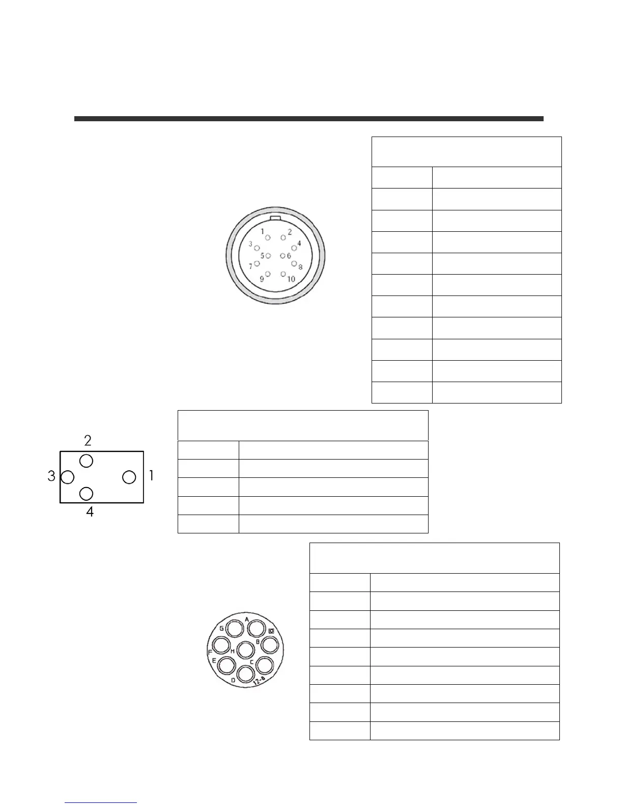
Appendix B System and Cable Diagrams
Sonar / Pan and Tilt Cable
10 Pin Connector to Sonar (Impulse MKS-
310-CCP-RA)
Pin
Function
1
Ethernet RX+ (to sonar)
2
Ethernet RX- (to sonar)
3
Ethernet TX+ (to sonar)
4
+24V DC
5
+24V DC
6
Ethernet TX- (to sonar)
7
Ground
8
Ground
9
N/C
10
N/C
4 Pin Connector to Pan & Tilt Unit (Impulse LPMIL-4-
FS)
Pin Function
1 DC Common
2 +24V DC
3 Data B
4 Data A
8 Pin Connector to Sonar and Pan & Tilt Unit (Souriau
UTG612-8PN)
Pin Function
A Ethernet RX+ (to sonar)
B Ethernet RX- (to sonar)
C Ethernet TX+ (to sonar)
D +24V DC
E 24 DC Common
F Ethernet TX- (to sonar)
G Data A (to P&T)
H Data B (to P&T)