DLC50 Control Panel Installation and Operation Manual | Doc. No. 6051439500 Rev. A
Broadcast Microwave Services 7
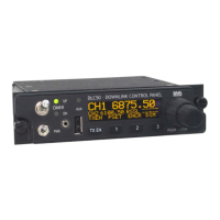
2. Connect the 4-pin power and 6-pin actuator cables of the wire harness to the appropriate rear-
panel connectors.
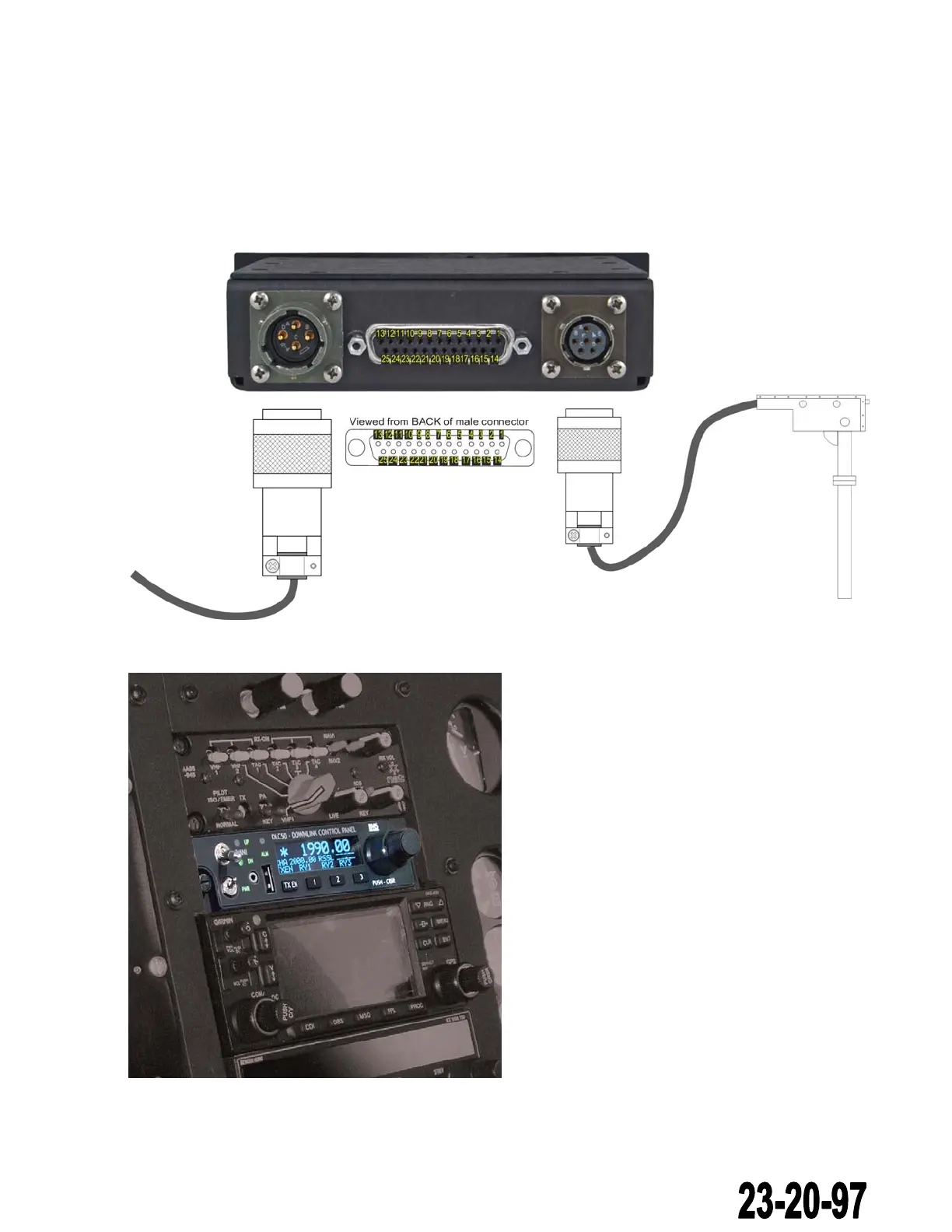
3. Position the DLC50 into its mounting slot in the control panel and turn fasteners ¼ turn to lock in
place. Consult Figure 5 for nominal panel size and dimensions.
4. Secure wire harness.
Figure 8. Basic connection diagram
Figure 9. Typical installation
The document reference is online, please check the correspondence between the online documentation and the printed version.