DLC50 Control Panel Installation and Operation Manual | Doc. No. 6051439500 Rev. A
Broadcast Microwave Services 9
2.3 Connectors and Pin-outs
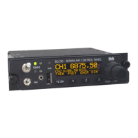
2.3.1 Power Cable Connector
Figure 11. DLC50 power connector
Table 3. Power connector pin-out (PT02E-12-4P)
PIN SIGNAL
PIN A 24-32 VDC IN
PIN B PA STBY/OPER
PIN C DC RTN (GND)
PIN D SYST PWR ON/OFF
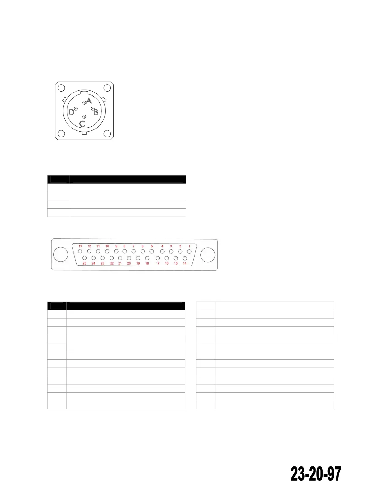
2.3.2 DB25-5 Connector
Figure 12. DB25-5 connector
Table 4. DB25-S connector pin-out
PIN SIGNAL
1 RS232 TXD COM3 (Receiver Command)
2 RS232 RXD COM3 (Receiver Status)
3 Data GND
4 RS232 TXD COM2 (Transmitter Command)
5 RS232 RXD COM2 (Transmitter Status)
6 Data GND
7 RS232 TXD COM0 (Remote Output)
8 RS232 RXD COM0 (Remote Input)
9 Data GND
10 TBD
11 TBD
12 TBD
13 TBD
14 0-28V External Dimmer Control Input
15 5VDC Switched Output (28 mA max)
16 28VDC Switched Output (28 mA max)
17 OC1 (open collector output 1)
18 OC2 (open collector output 2)
19 OC3 (open collector output 3)
20 OC4 (open collector output 4)
21 GND
22 GND
23 GND
24 GND
25 GND
The document reference is online, please check the correspondence between the online documentation and the printed version.