OZONE MONITOR BMT 932 Manual, Rev. 02/2021
16
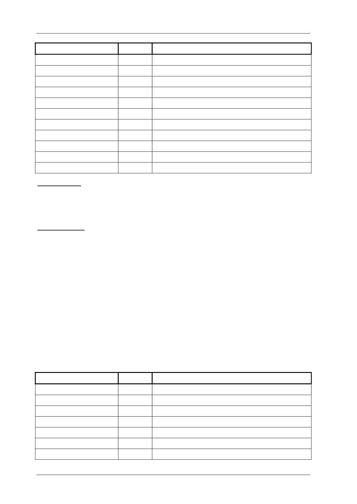
Signal Name Pin No. Description
Alarm High Open 6 Pins 4-6 opened when HIGH alarm
4-20 mA (GND) 7 Current loop output return
4-20 mA 8 Current loop output
Voltage Outputs (GND) 9 Voltage outputs return
Voltage Output 1 V 10 Max. concentration Range = 1 V
Voltage Output 10 V 11 Max. concentration Range = 10 V
Lamp Low 12 Relay contact
Lamp Low 13 Pins 12-13 open when LAMP LOW
Error Common 14 Relay contact
Error Closed 15 Pins 14-15 closed when error
Error Open 16 Pins 14-16 opened when error
Relay Outputs: the Alarm Relay contacts will operate at a max. voltage of 28 V (DC or AC) and a
max. current of 1 A. Further details of the Alarm Relays operation are described in section 15 on
page 31. The Error Relay and Lamp Low Relay will switch 28 V (AC or DC) at a max. current of
1 A. All relays are in the alarm/error position if no power is applied to the instrument.
Analog Outputs: The analog outputs are updated with every new measurement (about every 20
seconds).
The voltage outputs are isolated voltage signals 0 to 10 V and 0 to 1 V, proportional to the con-
centration (actually the 0 - 10V signal swings down to about -0.25 V below zero). Input resistance
of the load should be higher than 1 k.
The current output is an isolated current signal 4 to 20 mA, proportional to concentration (with
an offset of 4 mA). Input resistance of the load should be less than 600 (optional 1350 ).
The current output provides the energy for the curent loop. Attention:
The current output must not be connected to an external power supply !
11.3 Channel Identification
The green terminal block named "CHANNEL ID” provides six semiconductor relay contacts
with information on which sample channel the analog output concentration signal corresponds
to. A closing relay identitfies a channel.
Signal Name Pin No. Description
Channel 1 1 Output from sample on Channel 1
Channel 2 2 Output from sample on Channel 2
Channel 3 3 Output from sample on Channel 3
Channel 4 4 Output from sample on Channel 4
Channel 5 5 Output from sample on Channel 5
Channel 6 6 Output from sample on Channel 6
Common 7 Common contact for all relays