6
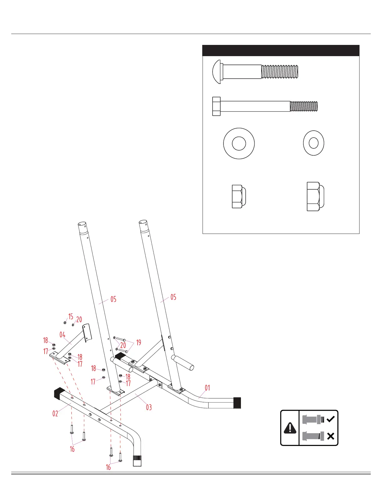
Assembly STEP 2
With the help of an assistant, align and attach the Upright
(#05) to the Base Frame (Right) (#02). Insert two Carriage
Bolts (#16) through the Base Frame (Right) (#02) and
Upright (#05). Secure them together using two Washers
(#17) and two Lock Nuts (#18). Repeat this process on the
other side.
Align and attach the Upright Angle Support Frame (#04) to
the Upright (#05) and Base Frame (Right) (#02). Insert two
Carriage Bolts (#16) through the bottom of the Base Frame
(Right) (#02) followed by the Upright Angle Support Frame
(#04).
At this point hand tighten the two Washers (#17) and two
Lock Nuts (#18) on the lower portion as it may be dicult to
align the holes for the upper portion. Insert two Bolts (#19)
through two Curved Washers (#20) followed by the Upright
(#05), and Upright Angle Support Frame (#04). Secure them
together using one Curved Washer (#20) and one Lock Nut
(#15). Repeat this process on the other side.
Now secure the Lock Nuts (#18) that were hand tightened in
the lower portion. Repeat this process on the other side.
Hardware Required
#16. Carriage Bolt (M10x65 mm) [8 pieces]
#19. Bolt (M8x70 mm) [4 pieces]
#17. Washer (M10)
[8 pieces]
#20. Curved Washer (M8)
[6 pieces]
#15. Lock Nut (M8)
[14 pieces]
#18. Lock Nut (M10)
[8 pieces]
 Loading...