7
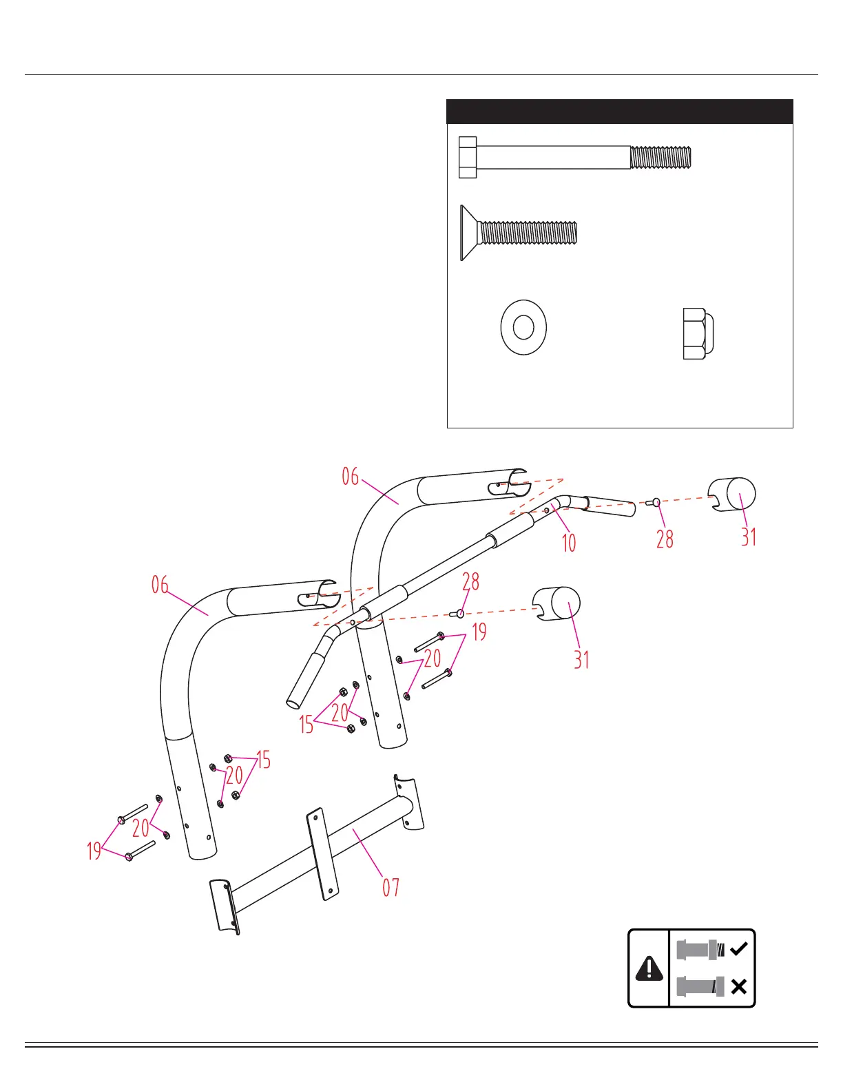
Assembly STEP 3
Align and attach the L Shaped Upper Frame (#06) to the
Back Pad Support Frame (#07) as illustrated in the diagram.
Insert two Bolts (#19) through two Curved Washers (#20)
followed by the L Shaped Upper Frame (#06) and Back
Pad Support Frame (#07). Secure them together using two
Curved Washers (#20) and two Lock Nuts (#15). Repeat this
process on the other side.
Insert the Pull Up Handlebar (#10) into both L Shaped Upper
Frame (#06) and secure it using two Screws (#28) directly
into the L Shaped Upper Frame (#06) as illustrated. Slide
the Upper Frame End Cap (#31) over the Pull Up Handlebar
(#10) and both the L Shaped Upper Frames (#06).
Hardware Required
#19. Bolt (M8x70 mm) [4 pieces]
#28. Screw (M8x35 mm) [2 pieces]
#20. Curved Washer (M8)
[8 pieces]
#15. Lock Nut (M8)
[4 pieces]
 Loading...