8
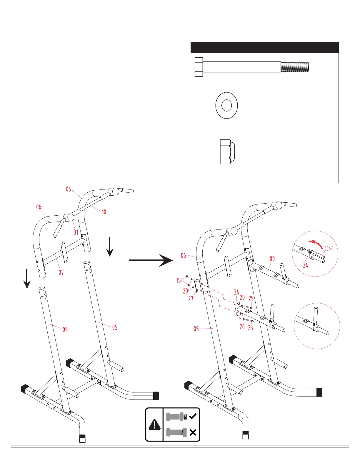
Assembly STEP 4
With the help of an assistant, slide the L Shaped Upper
Frames (#06) into the Uprights (#05) as oriented in illustration
indicated below. Insert two Bolts (#25) through two Curved
Washers (#20) followed by the VKR Arm Rest Support
Frame-Right (#34), L Shaped Upper Frame (#06), Upright
(#05) and Curved Shaped Metal Plate (#27). Secure them
together using two Curved Washers (#20) and two Lock
Nuts (#15). Repeat this process on the other side.
Next, to properly assemble the VKR Handlebar (#08), please
lift the right VKR Handlebar (#08) so that it is vertically
perpendicular to the two holes on the VKR Arm Rest Support
Frame-Right (#34).
Insert the VKR Handlebar (#08) down through both holes.
Please jiggle the VKR Handlebar (#08) a little to ensure it is
fully inserted. Repeat on the opposite side.
Hardware Required
#25. Bolt (M8x75 mm) [4 pieces]
#15. Lock Nut (M8) [4 pieces]
#20. Curved Washer (M8) [8 pieces]
Lift as shown
Correct Assembly
 Loading...