Note:
All Pulleys in this step are 4 1/4” diameter.
Leave all pulley bolts hand tight until step 12 is completed.
A. See diagram 1. Attach either end of Seated Press Cable (22) to Angled Support Pillar (E) as
shown using:
One 43 (3/8” x 2 1/2” hex head bolt)
Two 53 (3/8” flat washer)
One 52 (3/8” nylon lock nut)
B. Route Cable (22) through the pulley bracket on Bench Press Frame (J) and install Pulley (D1)
as shown using:
One 45 (3/8” x 1 1/2” hex head bolt)
One 52 (3/8” nylon lock nut)
C. Route Cable (22) through Angled Support Pillar (E) as shown in diagram 1.
D. Route Cable (22) through pulley bracket where Pulley (D2) will be installed and hold cable in
place by installing Pulley (D2) as shown in diagram 2 using:
One 45 (3/8” x 1 1/2” hex head bolt)
One 52 (3/8” nylon lock nut)
E. Connect the end of Cable (22) to the hook on the bottom of Single Pulley Hook (W) as shown in
diagram 1.
11
Be careful to assemble all components
in the sequence they are presented.
mm
Inch
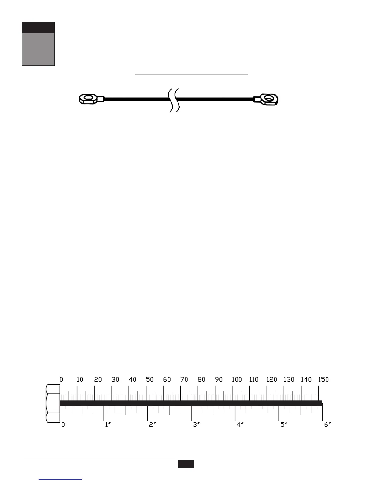
22
Seated Press Cable (22)
Stamped Eye End
Stamped Eye End
1440 mm 4’ 8.5”
STEP