12
Be careful to assemble all components
in the sequence they are presented.
mm
Inch
24
STEP
A. Route Cable (29) over the top and around pre-installed Pulley (B8) and toward the Left Seated
Press Arm (L).
Route Cable (29) under
and around Pulley (B9) and install Pulley (B9) into the bottom pulley
holder on the Left Seated Press Arm (L) using:
One 52 (3/8” x 1 3/4” hex head bolt)
Two 74 (3/8” washer)
One 72 (3/8” nylon lock nut)
B. Route Cable (29) under and around pre-installed Pulley (B10) and back toward the Left Seated
Press Arm (L).
Route Cable (29) under
and around Pulley (B11) and install Pulley (B11) into the top pulley holder
on the Left Seated Press Arm (L) using:
One 52 (3/8” x 1 3/4” hex head bolt)
Two 74 (3/8” washer)
One 72 (3/8” nylon lock nut)
C. Route Cable (29) under and around pre-installed Pulley (B12) as shown.
Slide Oilite Washer (107) onto the top of Vertical Frame (J) as shown.
Attach Pivoting Pulley Holder (BD) onto the left
side of Vertical Frame (J) using:
One 105 (1/2” x 3/4” allen bolt)
One 73 (1/2” washer)
Route High Pulley Cable (29) through the Pivoting Pulley Holder (BD) at the top of Vertical Frame (J).
D. Install Pulley (B13) into the Pivoting Pulley Holder (BD) at the top of Vertical Frame (J) under
Cable (29) using:
One 106 (3/8” x 1 3/4” allen head bolt)
Two 74 (3/8” washer)
One 72 (3/8” nylon lock nut)
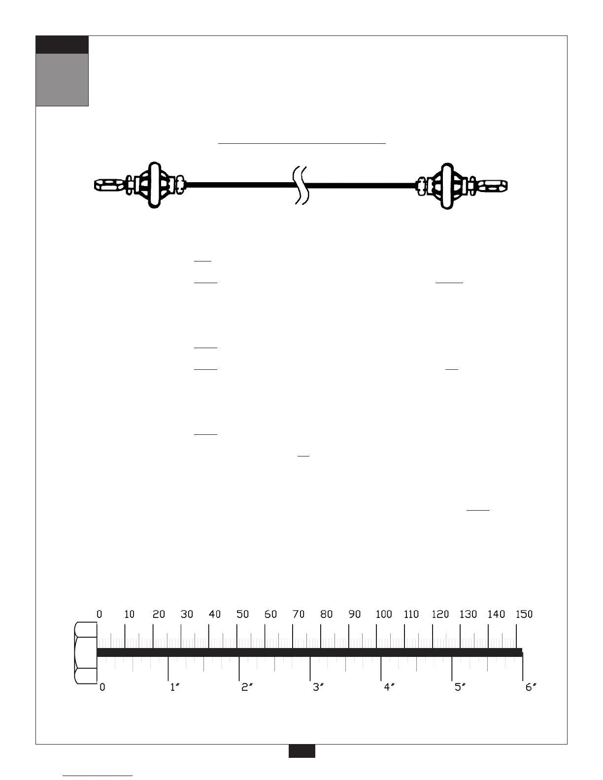
High Pulley Cable (29)
Ball Stop End
Ball Stop End
6925 mm
22’ 8”