13
STEP
Be careful to assemble all components
in the sequence they are presented.
mm
Inch
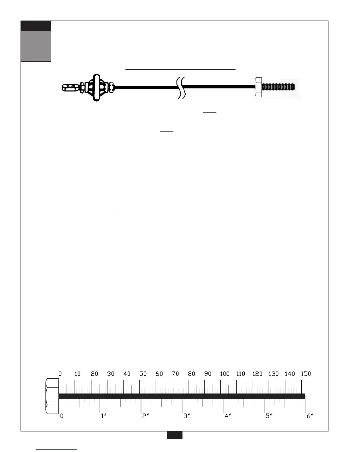
26
Ball Stop End
Threaded End
4455 mm
14’ 7”
Leg Extension Cable (30)
A. Route the threaded end of the Leg Extension Cable (30) under pre-installed Pulley (C1) and
through Leg Extension (W).
B. Route the threaded end of Cable (30) under
pre-installed Pulley (C2) and through Front
Base Frame (C).
C. Route the threaded end of Cable (30) through the opening in Front Base Frame (C), and between
the two Low Side Panels (D).
D. Route Cable (30) around Pulley (C3) and install Pulley (C3) between the two Low Side Panels (D)
using:
One 47 (3/8” x 4” hex head bolt)
Two 5 (spacer sleeve)
Two 74 (3/8” washer)
One 72 (3/8” nylon lock nut)
E. Route Cable (30) up to the Double Pulley Holder (BB).
Route Cable (30) around Pulley (C4) and install Pulley (C4) into the Double Pulley Holder (BB)
using:
One 52 (3/8” x 1 3/4” hex head bolt)
Two 74 (3/8” washer)
One 72 (3/8” nylon lock nut)
F. Route Cable (30) down and around Pulley (C5).
Install Pulley (C5) between the two Low Side Panels (D) using:
One 47 (3/8” x 4” hex head bolt)
Two 5 (spacer sleeve)
Two 74 (3/8” washer)
One 72 (3/8” nylon lock nut)
 Loading...