14
Be careful to assemble all components
in the sequence they are presented.
STEP
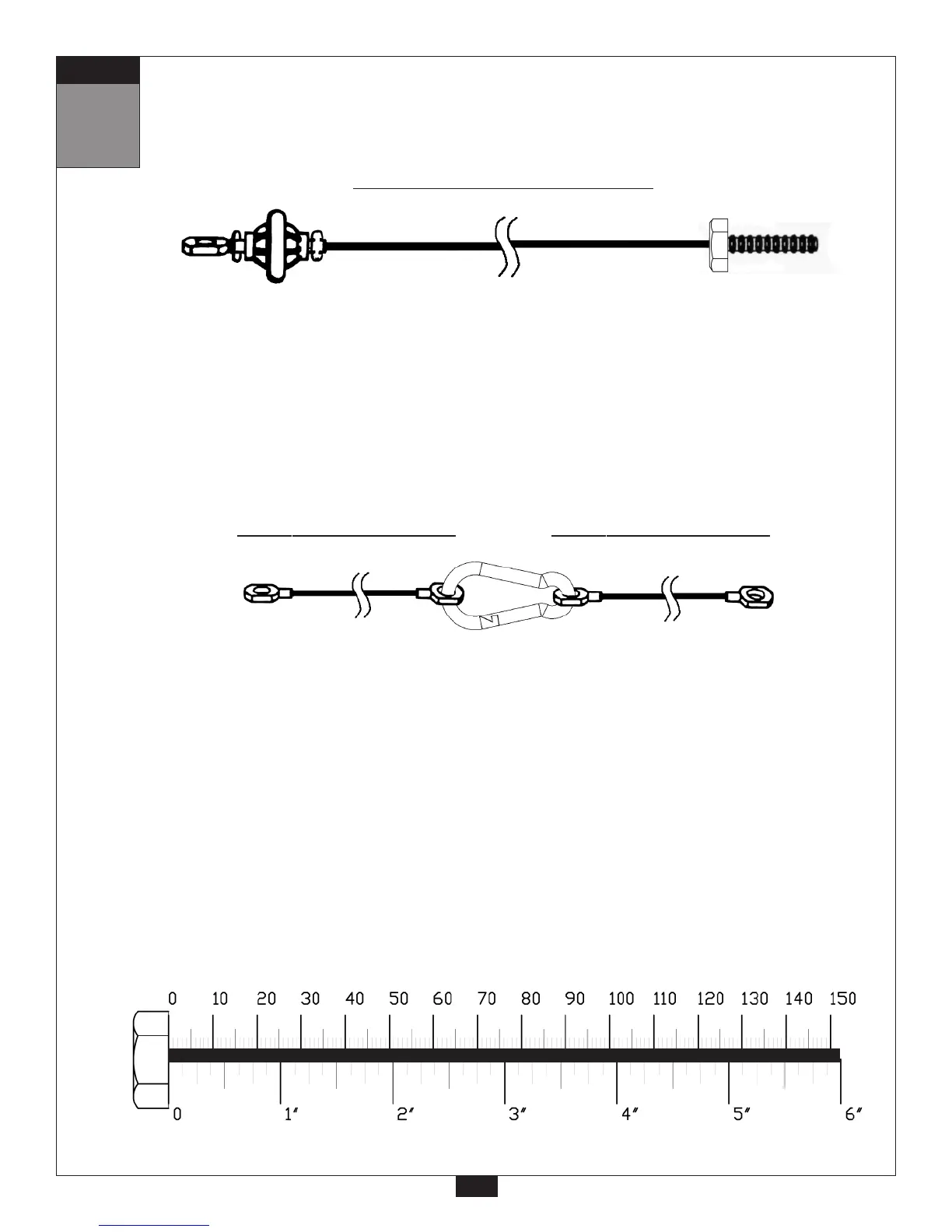
Stamped Eye End
Stamped Eye End
810 mm
2’ 6”
Short Cable-A (27) Short Cable-B (31)
mm
Inch
A. See Diagram 1. Connect the Threaded End of Cable (30) to Single Pulley Holder (BE). *
*Note:
Make sure Cable (30) is threaded a minimum of 1/2” into the Single Pulley Holder (BE)
and Jam Nut (70) tightened securely against spring lock washer (76) to ensure proper
connection. Check the Jam Nut (70) once a week to make sure it is tight.
B. See Diagram 2.Install two bolts as shown to hold cable around Pulleys (C3) and (C5) using:
Two 47 (3/8” x 4” hex head bolt)
Four 74 (3/8” washer)
Two 72 (3/8” nylon lock nut)
C. Connect the two short cables together with a Snap Link (16) to make one cable as shown above.
See Short Cable Diagram. Attach stamped eye end of Short Cable (27) to the bottom of Single
Pulley With Hook (BC) as shown.
Attach the other Stamped Eye End of Cable (31) to Main Base Frame (A) as shown using:
One 46 (3/8” x 4 1/4” hex head bolt)
Two 74 (3/8” washer)
One 72 (3/8” nylon lock nut)
4455 mm
14’ 7”
Ball Stop End
Threaded End
Leg Extension Cable (30)
2’ 8”
757 mm
28
 Loading...