4
Be careful to assemble all components
in the sequence they are presented.
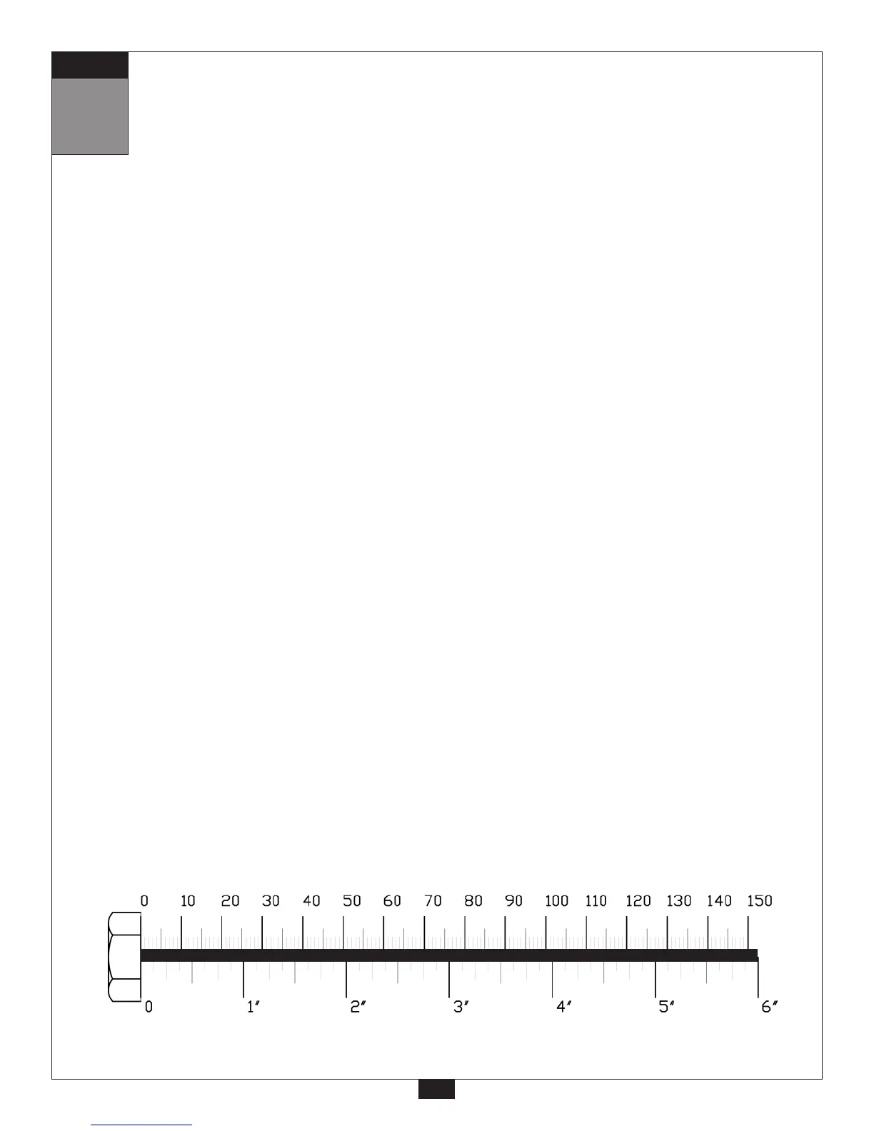
mm
Inch
8
STEP
A. Attach Right Seated Press Arm (K) and Left Seated Press Arm (L) to Vertical Frame (J) With
Shaft (128) using:
Two 39 (1/2” x 3/4” hex head bolt)
Two 73 (1/2” washer)
Tighten Allen Screws (111) in Vertical Frame (J).
B. Attach two Round End Caps (26) to Left Seated Press Arm (L), and attach two Round
End Caps (26) to Right Seated Press Arm (K) as shown.
C. Attach Pivot (P) to Right Seated Press Arm (K) using as shown:
Two 81 (3/8” x 5/8” allen bolt)
Two 82 (3/8” washer)
D. Attach Right Press Handle (M) to Pivot (P) on Right Seated Press Arm (K) using Shaft (129)
as shown:
Two 81 (3/8” x 5/8” allen bolt)
Two 82 (3/8” washer)
E. Attach Pivot (P) to Left Seated Press Arm (L) using as shown:
Two 81 (3/8” x 5/8” allen bolt)
Two 82 (3/8” washer)
F. Attach Left Press Handle (N) to Pivot (P) on Left Seated Press Arm (L) using Shaft (129) as shown:
Two 81 (3/8” x 5/8” allen bolt)
Two 82 (3/8” washer)
G. Attach Press Handle Holder (139)* to Right Seated Press Arm (K) using:
One 85 (3/8” x 3 1/4” allen head bolt)
Two 74 (3/8” washer)
One 72 (3/8” nylon lock nut)
*NOTE:
One Press Handle Holder (139) is marked with an R, and should be installed with the R
on top.
H. Attach Press Handle Holder (139)* to Left Seated Press Arm (L) using:
One 85 (3/8” x 3 1/4” allen head bolt)
Two 74 (3/8” washer)
One 72 (3/8” nylon lock nut)
*NOTE:
One Press Handle Holder (139) is marked with an L, and should be installed with the L
on top.