(1) Make sure that the signal is not caused by too much couplant. Clean the inspection area of all
couplant and then put only a small quantity of couplant on the inspection area. Do the inspection
one more time. If the ultrasonic signal was caused by too much couplant, it will be gone. If the
ultrasonic signal does not go away, continue to Paragraph 6.B.(2).
(2) It is possible that a surface condition has caused the signal. Look at the inner diameter of the fuse
pin at the approximate location where the ultrasonic indication occurs. Try to finger-dampen the
ultrasonic signal. Put a small quantity of couplant on your finger and rub the inner diameter of the
fuse pin at the location where the ultrasonic signal occurred. The signal will move up and down a
large amount if a surface condition has caused the ultrasonic signal. If the ultrasonic signal can
not be dampened, reject the fuse pin.
C. Make a record of all ultrasonic signals that are less than 40% full screen height and between 10% and
30% full screen width so you can refer to these records when you do this inspection again.
D. To make sure that the ultrasonic signals are not caused by sound transfer into the wing attach fitting,
do one of the steps that follow:
(1) Lift the engine and pylon to remove the load from the fuse pin. Refer to Service Bulletin
747-54A2153 for instructions on how to remove the weight of the engine and pylon from the fuse
pin. Do the inspection again. If the ultrasonic signal does not change to less than 40% full screen
height, reject the fuse pin.
(2) Remove the pin from the airplane. Do a magnetic particle inspection as specified in Service
Bulletin 747-54A2153.
E. To make sure there are cracks when you get ultrasonic indications with the fuse pin installed, do an
eddy current inspection as specified in Part 6, 51-00-00, Procedure 13. It will be necessary to first
remove all cadmium and corrosion from the inner diameter of the fuse pin. Refer to Service Bulletin
747-54A2153 for instructions on how to remove the cadmium and corrosion and how to refinish the
fuse pin after the inspection is done. To make sure there are cracks when you get ultrasonic indications
with the fuse pin removed from the airplane, do a magnetic particle inspection as specified in Service
Bulletin 747-54A2153.
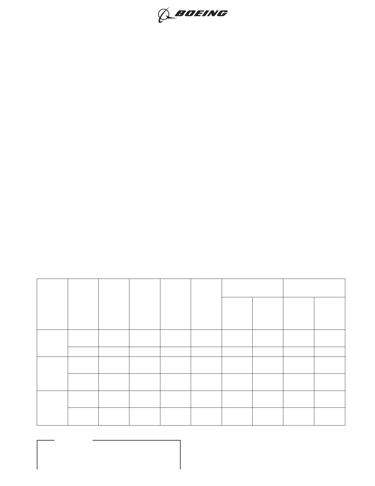
Table 1: Diagonal Brace - Calibration Information
ENGINE
CONFIGURATION
FUSE PIN
*[1]
STRUT
*[2]
REFERENCE
STANDARD
(Figure 2
&
Figure 3)
TRANSDUCER
DIAMETER
IN. (MM)
GUIDE
NUMBER
Figure 4
REFERENCE
NOTCH BACK SURFACE
TRANSDUCER
POSITION
POSITION
OF
SIGNAL
%FSW
*[3]
TRANSDUCER
POSITION
POSITION
OF
SIGNAL
%FSW
*[3]
JT9D-70 -10 I/B NDT4108 0.19 (4.8) NDT4108/
9-G3
B 11% C 62%
-11 O/B NDT4107 0.14 (3.6)NDT4107-G5 C 19% B 80%
JT9D-XXX
(EXCEPT
-70)
-13 I/B NDT4108 0.19 (4.8) NDT4108/
9-G4
D 13% E 70%
-6 O/B NDT4108 0.19 (4.8) NDT4108/
9-G4
D 13% E 70%
CF6-45,
-50
-5 I/B NDT4108 0.19 (4.8) NDT4108/
9-G3
D 13% E 70%
-6 O/B NDT4108 0.19 (4.8) NDT4108/
9-G4
D 13% E 70%
747
NONDESTRUCTIVE TEST MANUAL
PART 4 54-30-06
Page 4
Nov 15/2015D6-7170
ECCN 9E991 BOEING PROPRIETARY - Copyright © Unpublished Work - See title page for details
EFFECTIVITY
ALL