Input Connections
4
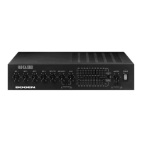
MIC 1- 4 (Rear Panel; #21 and #22)
MIC 1 through 4 utilize female XLR-type microphone connectors. A slide
switch located above each XLR connector is used to supply phantom
power for condenser microphones.
MIC 5/TEL (Rear Panel; #8 and #9)
The MIC 5/TEL input is designed to accept input from a microphone or
from a telephone line. A slide switch is provided to select MIC 5 or TEL
input. To connect a microphone, place the MIC 5/TEL switch in the MIC
position. Use two conductor shielded cable and connect the cable shield
to the center GND terminal. To use the TEL input, place the MIC 5/TEL
switch in the TEL position and connect the 600-ohm telephone paging
source (dry signal only - no DC voltage) to the MIC 5/TEL screw terminals.
See page 5 for Phantom Power for MIC 5.
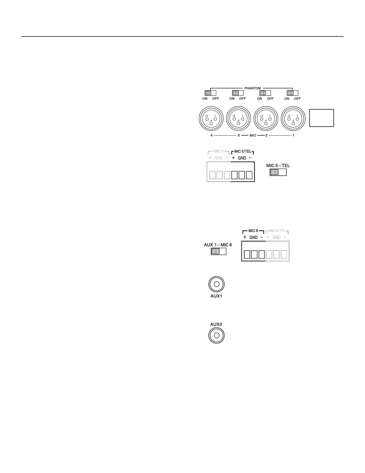
MIC 6/AUX 1 (Rear Panel; #6, #7, #20)
The MIC 6/AUX 1 input is designed to accept input from a microphone
using terminal strip connections or from a high level auxiliary source such
as a tuner or CD player using the AUX 1 RCA jack. A slide switch is used
to select input type. Connect a microphone to the screw terminals labeled
MIC 6 (works only when AUX 1/MIC 6 switch is in the MIC 6 position).
Use two conductor shielded cable and connect the cable shield to the
center GND terminal. Connect an auxiliary input source to the AUX 1
RCA jack (only works when the AUX 1/MIC 6 switch is in the AUX1
position.) See page 5 for Phantom Power for MIC 6.
AUX 2 (Rear Panel; #19)
The AUX 2 input uses an RCA plug and accepts input from a dedicated
AUX source
.
Installation Note
Keep input leads away from the output leads and AC power cables. Unless the driving source provides a low-impedance output,
keep the input lead under ten feet in length. Make all connections to the unit with the POWER switch in the OFF position
1 — GND
2 — +
3 — –
 Loading...