3 Technical Data
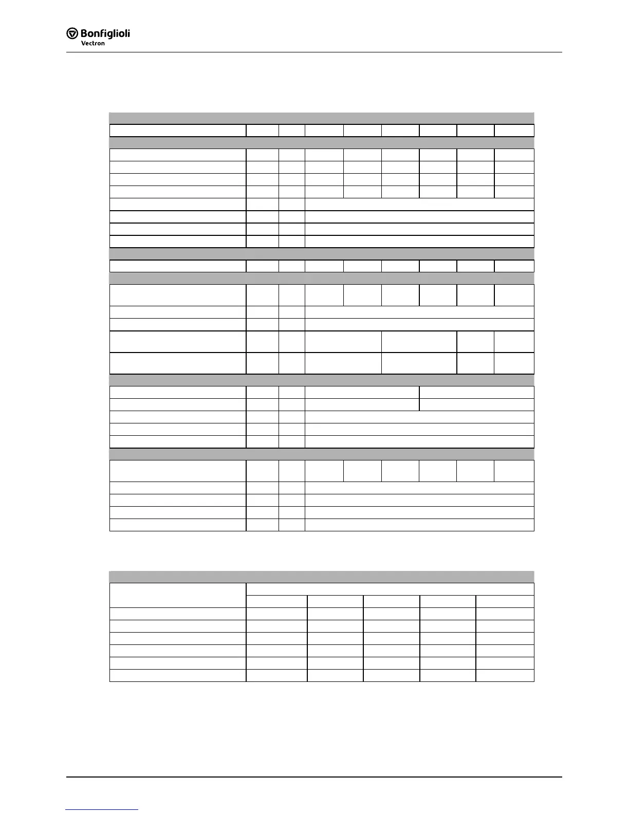
3.1 Frequency Inverter 230 V (0.55 to 3.0 kW)
Type
ACT 201 -05 -07 -09 -11 -13 -15
Output, motor side
Recommended shaft output P kW 0.55 0.75 1.1 1.5 2.2 3.0
4)
Output current I A 3.0 4.0 5.4
5)
7.0 9.5 12.5
4) 5)
Overload current (60 s) I A 4.5 6.0 7.3 10.5 14.3 16.2
Overload current (1 s) I A 6.0 8.0 8.0 14.0 19.0 19.0
Output voltage U V 3 x 0 ... mains voltage
Protection - - Short circuit / earth fault proof
Rotary field frequency f Hz 0 ... 1000, depending on switching frequency
Switching frequency f kHz 2, 4, 8
(nom. operat. point), 12, 16
Output, brake resistor
min. brake resistor (U
dBC
= 385 V) R Ω 230 160 115 75 55 37
Input, mains side
Mains current
3)
, 3ph/PE
1ph/N/PE ; 2ph/PE
I A
3.0
5.4
4.0
7.2
5.5
1)
9.5
2)
7.0
13.2
9.5
16.5
2)
10.5
1)
16.5
2) 4)
Mains voltage U V 184 ... 264
Mains frequency f Hz 45 ... 66
Fuse 3ph/PE
1ph/N/PE ; 2ph/PE
I A
6
10
10
16
16
20
16
20
UL type 250 VAC RK5, 3ph/PE
1ph/N/PE; 2ph/PE
I A
6
10
10
15
15
20
15
20
Mechanics
Dimensions: HxWxD mm 190x60x175 250x60x175
Weight (approx.) m kg 1.2 1.6
Degree of protection - - IP20 (EN60529)
Terminals A
mm
2
0.2 ... 1.5
Form of assembly - - vertical
Ambient conditions
Energy dissipation
(2 kHz switching frequency)
P W 43 53 73 84 115 170
Coolant temperature
T
n
°C 0 ... 40 (3K3 DIN IEC 721-3-3)
Storage temperature
T
L
°C -25 ... 55
Transport temperature
T
T
°C -25 ... 70
Rel. air humidity - % 15 ... 85; not condensing
If required by the customer, the switching frequency may be increased if the output current is
reduced at the same time. Comply with the applicable standards and regulations for this operating
point.
Output current
Switching frequency
Frequency inverter nominal power
2 kHz 4 kHz 8 kHz 12 kHz 16 kHz
0.55 kW 3.0 A 3.0 A 3.0 A 2.5 A 2.0 A
0.75 kW 4.0 A 4.0 A 4.0 A 3.4 A 2.7 A
1.1 kW 5.5 A
2)
5.5 A
2) 5)
5.4 A
2) 5)
4.5 A
2) 5)
3.7 A
5)
1.5 kW 7.0 A 7.0 A 7.0 A 5.9 A 4.8 A
2.2 kW 9.5 A
2)
9.5 A
2)
9.5 A
2)
8.0 A
2)
6.5 A
3.0 kW
2) 4)
12.5 A
1)
12.5 A
1) 5)
12.5 A
1) 5)
10.5 A
1) 5)
8.5 A
5)
1)
Three-phase connection requires a commutating choke.
2)
One- and two-phase connection requires a commutating choke.
3)
Mains current with relative mains impedance 1% (see chapter„Electrical installation“)
4)
Maximum output current is 9.5 A for one- and two-phase connection.
5)’
Switching frequency is reduced in thermal limit range
 Loading...


