5.6.2 Control Terminals – Terminal Diagram
The control hardware and the software of the frequency inverter are freely
configurable to a great extent. Certain functions can be assigned to the control
terminals, and the internal logic of the software modules can be freely selected.
In these brief instructions, the sensor-less control and the sensor-less field oriented
control are described in Configuration 110 and Configuration 410, respectively
5.6.2.1 Configuration 110 – Sensorless Control
Configuration 110 contains the functions for variable-speed control of a 3-phase
machine in a wide range of standard applications. The motor speed is set according
to the selected ratio of the reference frequency to the necessary voltage.
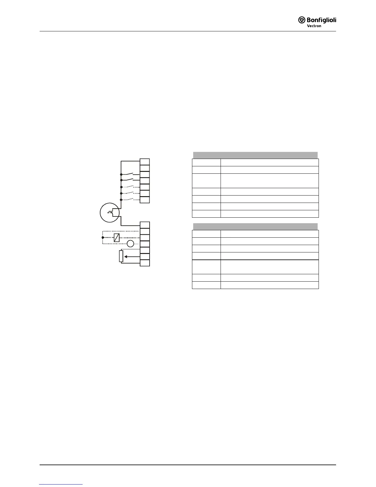
Control terminal X210A
X210A.1 Supply voltage +20V
X210A.2 Ground 20 V
X210A.3 Controller release / error acknowl-
edgment
X210A.4 Start of clockwise operation
X210A.5 Start of anticlockwise operation
X210A.6 Data set change-over 1
X210A.7 Data set change-over 2
Control terminal X210B
X210B.1 Motor thermal contact
X210B.2 Ground 20 V
X210B.3 Operating message
X210B.4 Analog signal of actual frequency
X210B.5 Supply voltage +10V
Reference value potentiometer
X210B.6 Reference speed 0 ...+10 V
GND 20 V
S1OUT
MFO1A
+10 V/ 4 mA
MFI1A
GND 10 V
1
2
3
4
5
6
7
X210A
+20 V/180 mA
GND 20 V
S1IND
S2IND
S3IND
S4IND
S5IND
S6IND
X210B
1
2
3
4
5
6
7
M
V
+
-
+
-
X210B.7 Ground 10 V
 Loading...


