9 / 32
IOM BX-BE-BN-MX-ME-M_eng - Translation of original instructions in Italian - Rev 02_0 - 30/09/16
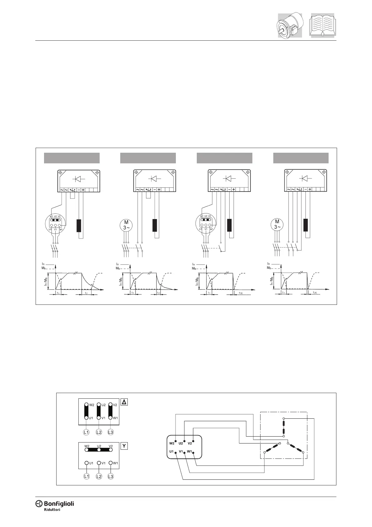
Scheme (A) - Brake power supply from motor terminals and a.c. line disconnection. Delayed stop
time t2 and function of motor time constants. Mandatory when soft-start/stops are required.
Scheme (B) - Separate supply of brake coil and a.c. line disconnect. Regular stopping time, inde-
pendent on time constants of motor.
Scheme (C) - Brake coil power supply from motor terminals and AC/DC line disconnection.
Scheme (D) - Brake coil with separate power supply and AC/DC line disconnection.
(A) (B) (C) (D)
Start
coil coil coil coil
Start Start StartStop Stop Stop Stop
U2
V a.c.±10% Hz P [W] I [A]
BN 71 M1
1~230
50/60
22 0.12
BN 80 M2
22 0.12
BN 90 —
40 0.30
BN 100 M3
3 ~ 230 / 400Y
40 0.12 / 0.09
BN 112 —
50 0.26 / 0.15
BN 132 ... BN 160MR M4
110 0.38 / 0.22
V a.c. ± 10% Hz P [W] I [A]
BE 80 ME2
1 ~ 230
50 / 60
22 0.12
BE 90 —
40 0.30
BE 100 ME3
3 ~ 230 / 400Y
40 0.12 / 0.09
BE 112 —
50 0.26 / 0.15
BE 132 ME4
110 0.38 / 0.22
Fan terminals are wired in the motor terminal box
4.7 FA and BA brake connections
The diagram below shows the wiring when brake is connected directly to same power supply of the motor:
Delta
connection
Star connection
Motor terminal board Brake
 Loading...