Installation
EN
bora.com 89
Fig.8.13
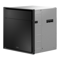
Connection diagrams
[1]
Connection diagram for 2-phase connection, 16 A
[2]
Connection diagram for 1-phase connection, 16 A
Do not use the bridges provided.
8.6.6
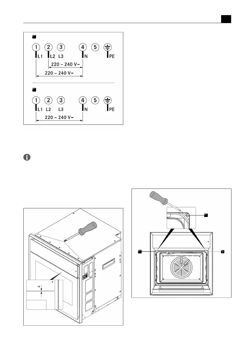
Positioning the operating unit
u
Ensure that there is an even distance of 4mm
between the operating unit and the door.
u
To do this, turn the adjusting screws on the front of
the top of the housing.
Fig.8.14
Adjusting the distance between the operating
unit and door
8.6.7
Positioning the appliance
u
Push the appliance into the desired position in the
installation recess. Ensure that the water hoses and
mains supply cable are not trapped or damaged in
doing so.
u
Maintain a minimum distance of 30mm between the
back of the appliance and the adjacent elements.
u
Position the appliance midway between the interior
walls of the installation recess.
u
Open the door.
u
Pull the oven seal away from the top left and top
right corners so that the fixing screw in each corner
is accessible.
T
Turning the fixing screw (4 mm Allen key) causes the
levelling shim on the corresponding side to move
outwards and press against the locking plate.
u
Tighten the screw until the shim is positioned
correctly.
u
Do the same on the other side.
u
Moisten the seal with water.
u
Press the oven chamber seal back inside the groove.
u
Check that the oven chamber seal is positioned
correctly all the way round.
u
Check that the appliance is installed correctly.
Fig.8.15
Securing the appliance
[1]
Oven chamber seal
[2]
Fixing screw